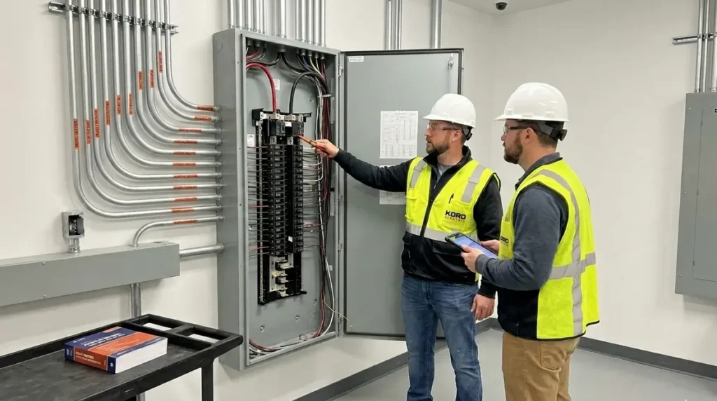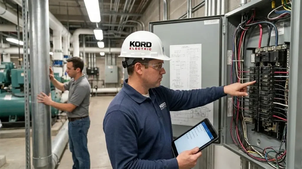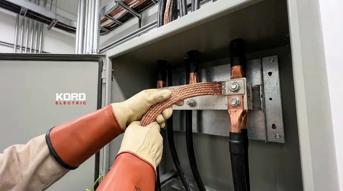
NFPA 70 Section 270.168 NEC DC bonding jumper 2 kV commercial
NFPA 70 Section 270.168 and NEC DC bonding jumper 2 kV: what commercial sites must know
At Kord Electric, we see a lot of confusion around how DC systems handle bonding. In particular, NEC DC bonding jumper 2 kV shows up in real designs whenever DC circuits operate above 2 kV and the code calls for proper bonding jumpers. Early on, others often assume “bonding” is just a box to tick. We do not. Instead, our technicians and expert service staff explain the goal in plain language: you bond so fault energy has a safe path, and you control stray voltage and corrosion risks before they become expensive downtime. And yes, skipping bonding is a bit like skipping the seatbelt, then acting surprised when things get loud.
In this article, a third person voice will guide you through NFPA 70 Section 270.168, the practical meaning of the rules, and how Kord Electric helps commercial and industrial facilities get it right the first time.
Why NFPA 70 cares about bonding above 2 kV
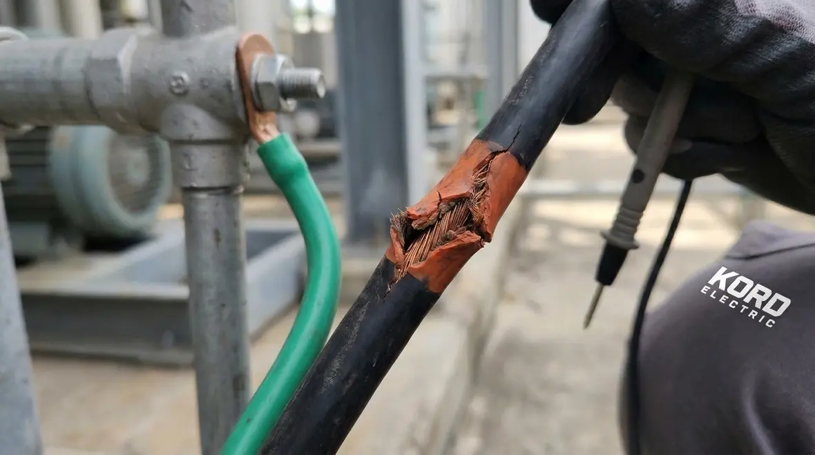
NFPA 70 Section 270.168 focuses on DC system bonding jumpers when DC voltage exceeds 2 kV. To keep things steady, the code requires bonding so that conductive parts remain at controlled potential during normal operation and during faults. As a result, a properly designed system reduces the chance that a person, maintenance worker, or nearby metal structure experiences hazardous voltage.
Also, DC systems can behave differently than AC systems. Even when a site expects a “smooth” DC voltage, a fault can change the story fast. Therefore, bonding is not only about protection of people. It also supports stable operation of protective devices and helps prevent unintended current paths that can degrade equipment.
Here is the key point: a bonding jumper is not decorative metal. It is a controlled connection plan that gives fault currents a predictable route. When that route is missing, loose, or made the wrong way, protective devices may not operate as intended. Then the site pays in service calls, shutdowns, and repairs. Nobody wants that kind of “surprise bill,” especially on a facility that runs because people trusted the design.
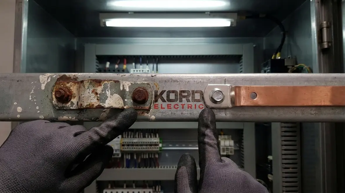
What Section 270.168 actually requires for DC bonding jumpers
Section 270.168 addresses when DC systems need bonding jumpers and how those jumpers connect system conductors and equipment. In most compliant designs, the bonding jumper concept helps equalize potential between the grounded or bonded parts and the metallic enclosures or conductive paths that must stay coordinated.
At Kord Electric, our approach starts with reading the requirement as a system rule, not a stand alone instruction. First, we identify what is the DC system, what parts are conductive and exposed, and what voltage level applies. Next, we map the bonding points so the jumper performs its role during abnormal conditions. Then we confirm that routing, connection methods, and termination details align with code intent.
From there, we also check how the facility design changes over time. A pro shop may add equipment. A control cabinet may move. A subpanel may get replaced. And if bonding was only “adequate” on day one, future changes can make the system non compliant. For commercial and industrial facilities, that is why our technicians treat bonding as an ongoing asset, not a one-time item.
Because bonding does not operate in isolation, facility teams often benefit from broader NEC context. Resources such as Kord Electric’s National Electrical Code explainers for the 2026 cycle and related grounding-focused articles help connect Section 270.168 to grounding electrode conductors, bonding jumpers, and other high-voltage rules that show up on the same project.
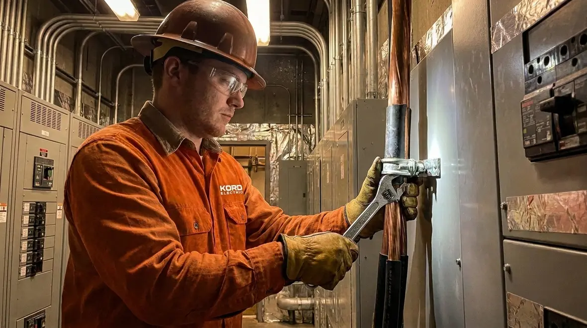
How bonding jumpers work in real fault conditions
To make the code rule practical, picture a fault. A cable insulation failure, a connector loosened by vibration, or a water intrusion can create an unintended conductive path. When that happens, fault current seeks the lowest impedance path. Now consider the surrounding metal parts: frames, enclosures, raceways, and other grounded conductive elements.
If bonding is correct, then fault current has a planned route. That planned route supports protective device operation and reduces the chance that metal parts rise to dangerous potential. If bonding is incorrect, then fault current may travel through unintended paths, including paths that pass close to people or pass through corrosion-prone areas that were never meant to carry current.
Additionally, DC faults can create more persistent conditions because DC does not naturally pass through zero like AC. So, the bonding jumper must stay effective under the stress the fault creates. In that sense, the NEC DC bonding jumper 2 kV requirement acts like a bridge. It helps the fault bridge safely back into the system design instead of improvising a route that nobody engineered.
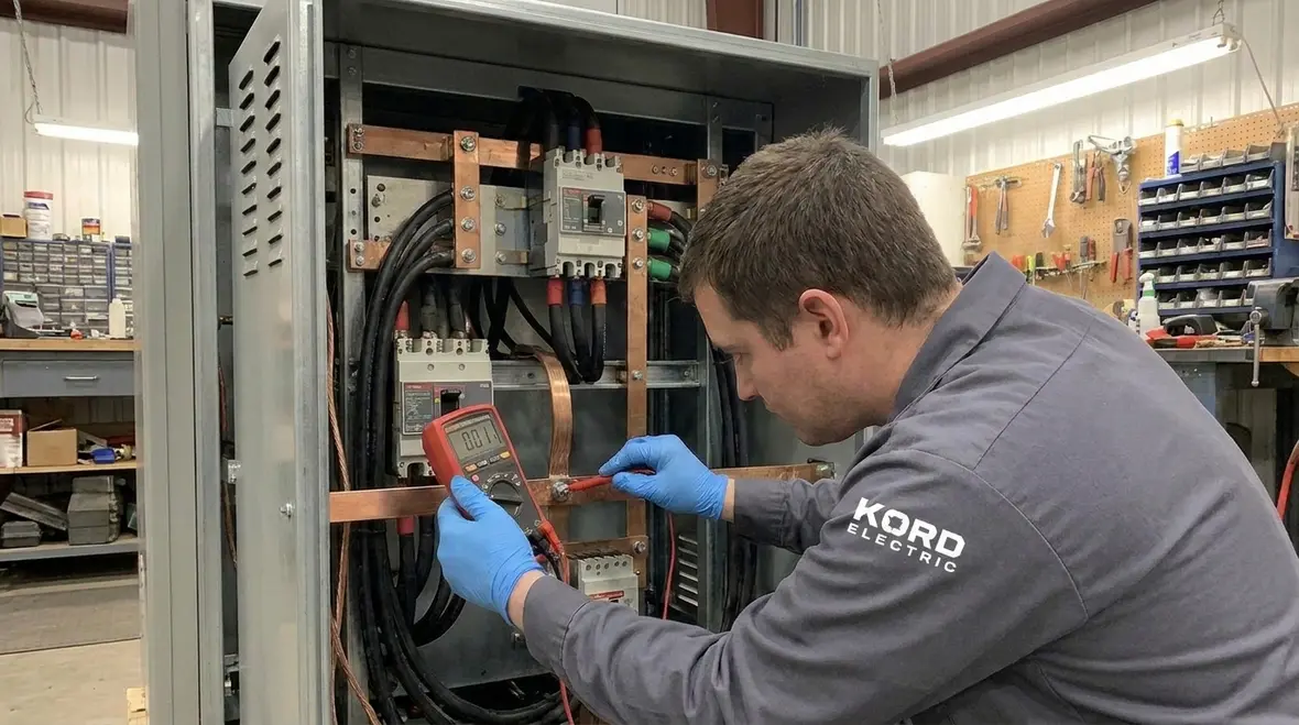
Common design and installation mistakes we see on major projects
When our expert service staff inspects commercial and industrial facilities, we notice patterns. First, some teams treat bonding as a separate trade item and stop coordination too early. However, bonding depends on how conductors, enclosures, grounding electrodes, and system components meet in the field.
Second, teams sometimes use incorrect connection methods. They may rely on paint covered surfaces, unlisted clamps, or thin bonding straps that do not match the mechanical and electrical requirements of the installation. Even when the metal looks connected, the electrical continuity can be unreliable. Then, during a fault, the jumper does not behave as intended.
Third, routing errors matter. A jumper installed in a way that forces tight bends, poor strain relief, or long runs through corrosive environments can fail early. The facility may never see the failure until it matters most.
Finally, we see “half bonding” when modifications happen. A later upgrade adds equipment, and the team bonds only what is convenient. Meanwhile, the earlier assumption about potential control no longer holds.
To keep projects stable, Kord Electric helps teams plan bonding early, verify details during installation, and document checks so the design stays correct after changes. For facility leaders working across multiple NEC topics, pairing this effort with resources like the Kord Electric blog’s National Electrical Code explainers and related NFPA 70 section guides makes it easier to align bonding, grounding, and overcurrent protection under one strategy.
How Kord Electric supports compliance for commercial and industrial DC systems
We serve commercial and industrial facilities and major property buildings. That focus matters because those projects involve engineered layouts, life safety stakes, and tight schedules. So our work centers on clarity, field verification, and practical documentation.
In practice, our technicians follow a deliberate sequence. First, we review the DC system layout and identify where bonding must occur based on voltage and equipment types. Next, we coordinate with electricians and electrical supervisors so the bonding jumper plan matches the installation method and termination details.
Then, we help ensure the bonding is not only installed, but also validated. We check continuity and connection quality as appropriate for the design. We also make sure bonding jumpers support the facility’s long term conditions, including vibration, moisture exposure, and maintenance access.
At the end, our expert service staff explains what we did and why it matters. We do it in plain terms, because the facility team should understand the system they operate. Nobody wants a binder full of diagrams that only one person can interpret. That is not engineering. That is a riddle. And riddle culture is not how you run a real facility.
For facilities planning broader upgrades, Kord Electric also connects DC bonding work with larger commercial electrical services across Los Angeles County. When bonding reviews happen alongside preventive maintenance, load studies, and other services, it becomes easier to schedule corrections and reduce downtime instead of chasing isolated issues later.
Quick reference: using a dual column checklist for DC bonding readiness
To help project teams move faster, we use a checklist mindset. Below is a dual column view that many commercial teams find useful during design reviews and field closeout.
| What to confirm | Why it matters |
|---|---|
| DC system voltage level and system boundaries | It determines whether the above 2 kV bonding jumper rules apply |
| Planned bonding points across enclosures and conductive paths | It helps control potential rise during faults |
| Bonding jumper routing and mechanical integrity | It supports durability in vibration and harsh areas |
| Termination quality and surface preparation | It reduces resistance and ensures continuity |
| Field changes and later equipment additions | It prevents “code drift” after upgrades |
FAQ: NFPA 70 DC system bonding and bonding jumpers
Final take: get DC bonding right before the system gets tested
DC bonding above 2 kV is not a “later” task, and NFPA 70 Section 270.168 is not a suggestion. We recommend you bring Kord Electric in early for commercial and industrial projects, because our technicians and expert service staff focus on correct bonding design, clean installation details, and practical field validation. If you want dependable fault performance and fewer shutdown surprises, contact us for a review and service plan. We will explain the requirements, then help you meet them.
If your facility is located in Southern California, Kord Electric’s dedicated Los Angeles County electrical services team can integrate DC bonding reviews with broader commercial electrical work. That way, bonding compliance, preventive maintenance, and system upgrades move forward under one coordinated plan instead of a patchwork of one-off fixes.