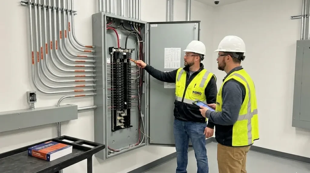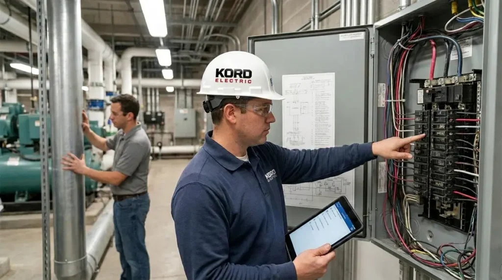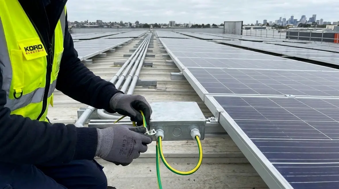
NFPA 70 Section 691.11 PV Station Bonding Grounding Guide
At Kord Electric, we help commercial and industrial facilities, and major property buildings, stay safe and code ready. In the opening we will anchor this guide to NFPA 70 Section 691.11 PV station bonding grounding, because it sets the tone for how PV systems connect, how fault current moves, and how metal parts stay at the right electrical potential. In other words, we focus on the “how electricity behaves” part, not just the “paper says so” part.
Our technicians and expert service staff explain the details in plain language, and we do it with care. After all, nobody wants to learn about bonding the hard way, like discovering the hard truth in a horror movie trailer. And yet, that is how many teams treat electrical code updates until someone gets hurt or production pauses.
Why NFPA 70 still matters for PV systems in 2026
NFPA 70, the National Electrical Code, keeps evolving so real job sites can stay safer. For commercial and industrial facilities, PV stations sit on rooftops, in parking canopies, and around utility tie-ins. These places see heat, vibration, and weather changes. Therefore, the code treats bonding and grounding as an ongoing safety system, not a one time install step.
When teams plan a PV station, they must think beyond panels and inverters. They must manage metallic parts, raceways, cable shields, grounding electrodes, and equipment enclosures so that, if a fault occurs, the system responds in a predictable way. If something goes wrong, protection devices must operate, and exposed metal should not become a shock hazard.
Kord Fire resources also emphasize how the NEC keeps the “big picture” in focus, including how conductors connect and how equipment gets protected. We do not just read the code; we apply it to real building conditions in major property projects. For facility leaders who want to zoom out and understand how all the rules fit together, we often point them to the Kord Electric blog resource on Understanding NFPA 70: The National Electrical Code Explained for 2026, then connect that bigger picture back to specific sections like 691.11 that drive PV station decisions.
NFPA 70, PV stations, and why “code” is really a behavior guide
NFPA 70 is sometimes treated like a stack of paperwork, but in real facilities it behaves more like a behavior guide for electricity. Articles and sections, including those that apply to PV stations, describe how current should travel, where it should return, and what should happen when something fails. Section 691.11 leans directly into that behavior: it defines how bonding and grounding should keep every exposed metal part on the same team when fault current shows up.
In 2026, code cycles are catching up with how fast PV deployment has grown. Large rooftop fields, canopies over parking lots, and ground mounted systems near utility tie ins now live next to sensitive controls, data rooms, and life safety circuits. When the code tightens its expectations for bonding and grounding, it is doing so because experience in the field has already proven what happens when those details get ignored.
What PV station bonding means in plain terms
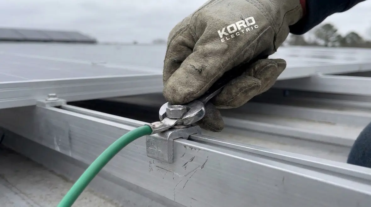
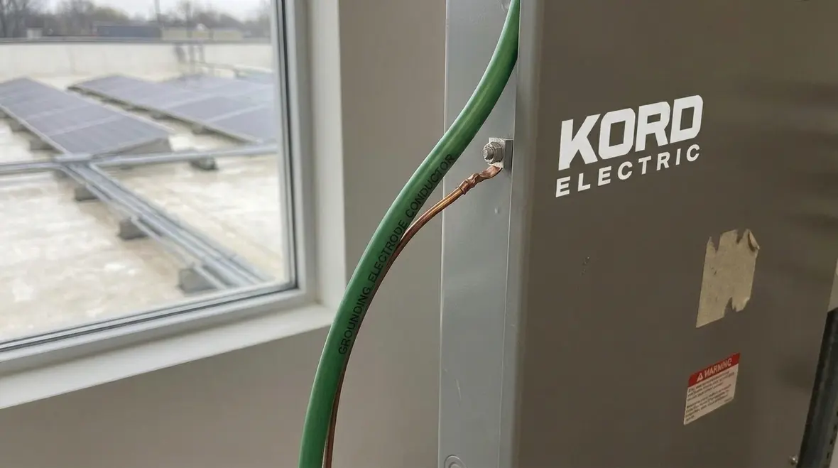
Bonding connects conductive parts together so they stay at the same electrical potential. So instead of metal parts floating at different voltages during a fault, we tie them together in a controlled way. Then grounding provides a path for fault current to flow safely into the earth or a grounding system.
For NFPA 70 Section 691.11 PV station bonding grounding, the intent is straightforward: build a reliable connection strategy across the PV station so that metallic components work as one system. That includes PV mounting structures, enclosures, cable trays, and other metal parts that could become energized.
Our technicians explain it like this: if bonding is the “team handshake,” grounding is the “escape route.” Both matter. Remove one and the whole plan turns into a comedy routine, except the punchline is an incident report.
Key pieces that bonding and grounding tie together
In practice, PV station bonding and grounding pull several major elements into a single, coordinated system:
Module frames and racking that must not sit at a different potential than nearby metal work or equipment enclosures.
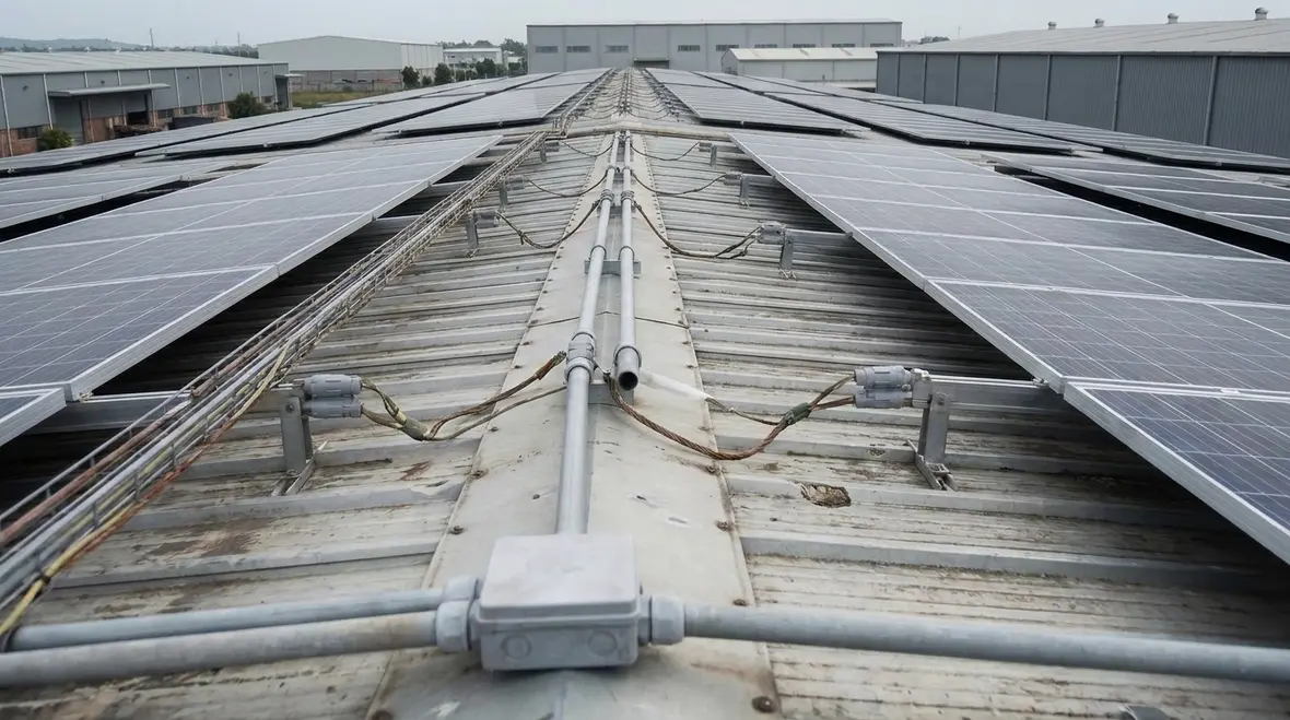
Raceways and cable trays carrying DC and AC conductors, which can become unintentional current paths if something fails.
PV combiners, disconnects, and inverters with metallic cases, knockouts, and mounting brackets that touch other building surfaces.
Grounding electrode systems that tie PV structures to building steel, rebar, or other electrode elements as the code requires.
Surge protective devices that rely on clear bonding paths so they can safely redirect transient energy away from sensitive electronics.
When all of those pieces share a consistent bonding and grounding strategy, a fault behaves like a scripted scene: it flows along known conductors, protective devices see it, and the system reacts. When the strategy is inconsistent or incomplete, the same fault behaves more like an improvised scene, and no one likes improvisation when energized metal is involved.
How Section 691.11 PV station bonding grounding drives safe connections
PV stations mix DC circuits, AC components, metal structures, and sometimes multiple grounding zones. Therefore, NFPA 70 Section 691.11 PV station bonding grounding pushes installers to think in terms of system interaction. It guides how equipment gets bonded so fault current returns through intended paths.
In practical terms, our service staff look for common problem spots:
Missing bonds between PV racking and grounding paths
Broken continuity through insulated mounting hardware where bonding must remain effective
Inconsistent bonding at raceways, cable trays, and enclosures
Loose connections that loosen over time due to thermal cycling and vibration
Unclear separation between PV system metal and building grounding where code requires defined connections
Then we verify that the bonding method supports fault detection and clearing. As a result, protective devices can clear the fault quickly, and exposed metal stays within safer limits. For commercial and industrial facilities, this directly supports uptime goals, because fewer faults mean fewer shutdowns.
How bonding and grounding interact with fault protection
Bonding and grounding alone do not clear faults; they create the conditions that allow overcurrent devices and protective relays to do their job. In PV stations, this means:
Fault current has a low impedance return path, so breakers and fuses see enough energy to trip correctly.
Exposed conductive parts rise together in potential during the fault, instead of creating dangerous step or touch voltages.
Ground fault detection systems do not “fight” random stray paths caused by loose or corroded bonds.
Surge protection devices can clamp and redirect transient currents along predictable routes.
When Section 691.11 is followed in both design and installation, the PV station behaves like an integrated electrical zone. When it is treated like a checklist item, teams end up chasing nuisance trips, confusing alarm logs, and “ghost” issues that only appear when the weather, loading, and switching events line up just wrong enough.
Bonding, grounding, and coordination with building systems
Commercial buildings rarely operate as electrical islands. PV stations integrate with service equipment, switchboards, grounding electrode systems, surge protection, and sometimes existing fire and life safety power paths. Therefore, the bonding and grounding approach must coordinate with the broader building design.
Our team uses a systems mindset. Instead of treating the PV array like a separate “mini project,” we align PV station grounding with the main service grounding method. This matters because fault current paths must be predictable across the entire facility.
Also, we pay attention to nearby metallic systems. Bonding must account for metal conduits, building steel when required, and equipment enclosures that tie into the same electrical environment. If a PV station connects to metal that the building treats differently, you can create conditions where parts do not move together electrically during a fault. Consequently, that can raise safety risks and complicate troubleshooting.
In major property buildings, there is another layer: maintenance access. Technicians work around arrays, inverters, and grounding points. So we design bonding and grounding layouts so that future inspections and testing stay realistic. In short, we build for today and tomorrow, not just for the first walkthrough.
Connecting PV stations to broader NEC strategy
Because PV stations touch service equipment, feeders, and building grounding, we often connect Section 691.11 conversations to broader NEC topics that Kord Electric covers in other resources. Owners and managers who want a wider view of how bonding and grounding play out across their facility can explore guides on how to read NFPA 70 effectively or how specific articles, like those covering cable ampacity or feeder guarding, influence real world installations. These resources help teams see that PV station grounding is not an isolated task; it is one chapter in the same code story that governs emergency power, surge protection, and maintenance planning.
Common installation gaps we see on commercial projects
Even skilled teams can miss details when they move fast. So we share the gaps our technicians see most often on commercial and industrial facilities and major property builds. Knowing these issues helps owner teams ask better questions, and it helps project teams plan inspections early.
Partial bonding: teams bond some modules and racking sections, but overlook other conductive parts that still require connection
Routing shortcuts: cable tray and raceway bonding get skipped or handled inconsistently across multiple runs
Unverified torque: connections fail over time when hardware does not meet proper tightness and material compatibility
Material mismatch: dissimilar metals without the right approach can corrode, and corrosion breaks electrical continuity
Testing not aligned with design: teams perform basic checks, but they do not confirm continuity and bonding pathways based on the as built layout
Meanwhile, code intent still holds steady. Bonding and grounding must deliver a dependable path for fault current and keep exposed metal safe. Our expert service staff help teams avoid “it looked fine on day one” problems, because day one is easy. Day two is where physics starts collecting receipts.
Why commercial PV stations need structured QA, not just visual checks
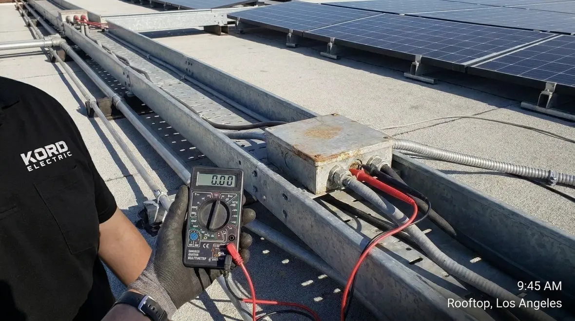
On a busy rooftop or canopy job, it is tempting to rely on quick visual checks. Hardware appears tight, cables look neat, and the racking lines up. But Section 691.11 performance depends on what meters, continuity tests, and torque verification find, not on what a quick glance suggests. Our QA approach for PV stations usually includes:
Targeted torque checks on bonding jumpers, lugs, and mechanical connectors on a documented sample basis.
Continuity testing for racking sections to confirm that multiple rows behave as one bonded structure.
Verification that listed bonding hardware is used where required, not swapped mid project due to site inventory.
Cross checks between drawings and as-built conditions so field changes do not leave “orphaned” metal elements.
Those steps take time, but they cost far less than unplanned outages, damage to inverters, or lengthy back-and-forth with inspectors when a grounding or bonding path does not match the design.
Inspection, testing, and documentation that owners can trust
After installation, teams need clear verification. Otherwise, the facility inherits uncertainty. For commercial and industrial facilities, uncertainty costs money and time, because it delays commissioning and complicates operations.
Kord Electric builds a practical documentation package. We track bonding and grounding points, document equipment connections, and support commissioning with test evidence aligned to the design intent. Then, during inspections, our technicians can point to the exact pathways used for bonding and grounding.
Moreover, we help facility managers understand what they should keep an eye on. Over time, PV components face thermal cycling and mechanical movement. So we recommend scheduled checks for bonding integrity and connection condition, especially where fasteners and junction points sit.
This approach matches how fire and electrical safety teams think. Resources like firepumps.org and related fire life safety training emphasize that the best protection is the one you can verify. Electrical safety also follows that rule, even when the equipment looks “static” from a distance.
Keeping PV stations ready for the next inspection cycle
Once a PV station passes initial inspections, it still has to pass the test of time. Weather, vibration, and maintenance work all press on bonding and grounding hardware. We encourage commercial owners to fold PV station checks into larger electrical preventive maintenance plans, so the same discipline that protects switchgear, feeders, and backup systems also protects roof level arrays and ground mounted equipment. That way, Section 691.11 compliance is not a snapshot; it becomes part of the facility’s long term safety story.
How to plan a PV station that stays code aligned
Planning reduces rework. And rework is expensive, especially when a commercial schedule hits deadlines like a freight train hits a timetable. So we recommend project teams take these steps early:
Review the applicable code cycle for the target installation year and expected updates
Map bonding and grounding points from racking to enclosures, then confirm continuity routes
Coordinate with structural and electrical design so metal parts get handled consistently
Design for maintenance access so technicians can inspect and test without dismantling large sections
Plan testing and documentation so commissioning does not stall
Next, we keep the conversation simple for decision makers. We translate code requirements into actions, then we verify the actions match the design. We do not hide behind vague statements. We show the connections, explain the purpose, and stand behind the work that supports safe operation in the field.
Integrating PV plans with broader electrical services
For many commercial and industrial owners, PV stations arrive alongside other upgrades: new distribution equipment, emergency power improvements, surge protection, or maintenance catch up. Kord Electric supports those programs with a service footprint that covers Southern California, including dedicated Los Angeles County electrical services for facilities that want coordinated design, installation, and long term support. When PV work is planned alongside broader electrical projects, bonding and grounding can be designed once and verified as a whole, instead of patched together in phases.
FAQ
What Kord Electric does for commercial and industrial teams
Kord Electric supports major property buildings with expert electrical services focused on safety, code compliance, and real world performance. Our technicians and service staff explain the “why,” confirm the “how,” and document the “what we did,” so your PV station does not become a long term mystery. If you are planning an upgrade or commissioning a PV system, we can help you align bonding and grounding with NFPA 70 requirements, reduce rework, and keep operations steady. Contact us for a project review today.
For facility leaders who want to connect PV station work to the rest of their code strategy, Kord Electric can pair Section 691.11 guidance with broader NEC support, emergency power planning, surge protection design, and preventive maintenance. That way, your PV station, switchgear, feeders, and life safety systems share the same approach to bonding, grounding, and documentation instead of operating as separate “chapters” in your electrical story.
If you are ready to coordinate PV station bonding and grounding with the rest of your electrical system, our team is ready to help you plan, build, and maintain a safer, more predictable installation.
Conclusion
NFPA 70 Section 691.11 PV station bonding grounding is more than a paragraph in a code book; it is a roadmap for how PV stations behave under real conditions. When bonding and grounding are planned carefully, integrated with the rest of the building, and verified over time, commercial and industrial facilities gain safer operations, fewer surprises, and better uptime. Kord Electric helps teams turn those rules into field-ready installations with clear documentation, practical testing, and service support across the life of the system.
Whether you are planning a new PV station, upgrading existing equipment, or reviewing your facility’s electrical strategy, aligning your design with Section 691.11 and broader NFPA 70 guidance keeps your projects grounded in more than just theory. It keeps them grounded in the way electricity actually behaves.
If you want a partner who treats bonding and grounding with the same seriousness you treat your production schedule and safety metrics, Kord Electric is ready to help you build a PV station that passes inspections, stands up to real operating conditions, and supports your long term goals.