NEC EGC Sizing Table and NFPA 70 Section 250.122
Kord Electric serves commercial and industrial facilities and major property buildings, and we handle electrical grounding with the kind of care that keeps inspectors calm and equipment alive. In the field, one of the first things our technicians check is whether the NEC EGC sizing table lines up with what Section 250.122 expects. For example, installers often look up the equipment grounding conductor (EGC) size for typical overcurrent device sizes, then move on. That is a start, but it is not the finish. In this article, third person coverage is our style, yet the message stays clear: we size EGCs correctly, we document our reasoning, and we avoid the “good enough” approach that causes rework later. And yes, mistakes in grounding are like leaving a tool in the panel. They always show up at the worst time, usually right when you are on a call with somebody important.
Why correct EGC sizing matters in Section 250.122
NFPA 70 Section 250.122 focuses on the sizing of equipment grounding conductors. Kord Electric treats this as more than a rule to memorize. It is a safety and performance requirement that directly affects fault clearing, bonding integrity, and long term reliability.
When a fault happens, the circuit must provide a low impedance path back to the source. If the EGC is undersized, the fault current may not clear quickly. Then you risk overheating, nuisance tripping, degraded insulation, and higher touch voltages. Conversely, oversized EGCs can also cause issues like cost overruns, conduit fill problems, and construction delays. So the goal is balanced sizing that follows the code logic.
Furthermore, Section 250.122 connects EGC sizing to the size of the overcurrent protection device and to conductor design assumptions. Kord Electric trains our expert service staff to read the section as an engineering intent, not a scavenger hunt. We explain what each part is trying to prevent, and we show how the field conditions affect the final choice.
How the NEC EGC sizing table guides real installs
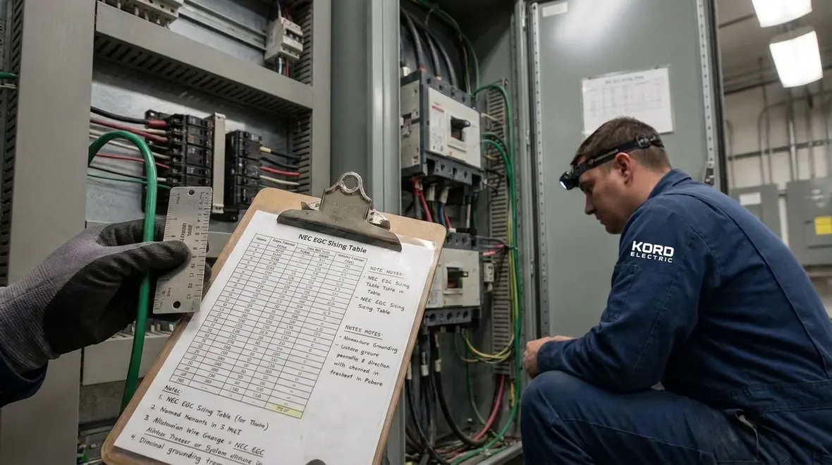
In many projects, the NEC EGC sizing table becomes the first stop because it offers quick sizing values. Still, Kord Electric emphasizes that the table must match the application path. Our technicians confirm the overcurrent device size, then select the conductor size that Section 250.122 allows for the equipment grounding conductor.
Then we verify installation details that can change the practical outcome. For instance, termination points, lugs, bonding bushings, and raceway types can influence what fits correctly. After all, a perfect number on paper still fails if the lug cannot accept the conductor or if the conduit routing violates spacing and fill rules. In addition, proper labeling and documentation help the next inspection go faster. Inspectors appreciate when the job file tells a consistent story.
So while the NEC EGC sizing table provides a strong baseline, we use it with a “measure twice, bond once” mindset.
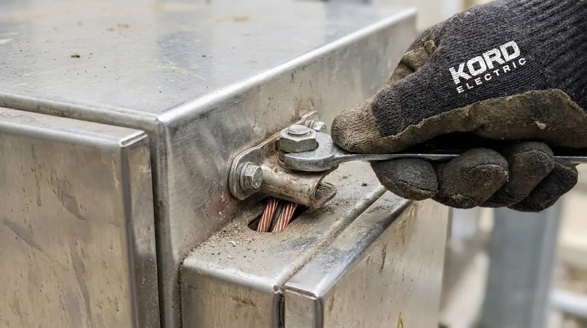
Step by step: sizing the EGC the way inspectors expect
Kord Electric uses a simple workflow. That reduces human error, and it keeps the reasoning visible. Our expert service staff often walks project leads through these steps in the field, because the fastest path to fewer corrections is shared understanding.
First, the team identifies the circuit conductors and the associated overcurrent device rating. Then we confirm the grounding and bonding method used for the installation. Next, we apply Section 250.122 logic to select the equipment grounding conductor size. After that, we check physical feasibility: conduit routing, conductor length, bends, and pull tension. Finally, we verify connections at equipment and at the service or subpanel bonding points.
To keep it clear, Kord Electric follows a documentation mindset:
- Record the overcurrent device size used for the EGC calculation.
- Record the chosen EGC size from the NEC EGC sizing table values.
- Note raceway type and termination method.
- Confirm bond continuity and torque values at terminations.
In short, we build an audit trail. If questions come up, the job does not freeze while somebody scrambles for answers. It keeps moving, like a well tuned HVAC system during a heat wave.
Corner cases that trip up commercial and industrial projects
Most grounding problems do not come from the big obvious steps. They come from the in between parts, the ones that feel small until they cause a big issue. Kord Electric sees these corner cases often in commercial and industrial buildings and major property structures.
Parallel raceways and multiple circuits. When there are many feeders or branch circuits, teams may unintentionally mix grounding conductor sizing assumptions. We make sure each circuit is handled with its correct overcurrent device basis. We also ensure bonding between sections stays continuous where required.
High fault current environments. Facilities with large transformers, generators, and high service short circuit current can intensify the consequences of wrong grounding sizing. If the EGC does not support fast fault clearing, equipment can see higher stress. Therefore, we align the EGC plan with the actual system design.
Switchgear, switchboards, and motor control centers. These assemblies include bonding points that must work as a system, not as a set of isolated parts. Kord Electric checks that the EGC path is continuous through the assembly bonding design and into the grounding electrode system. We also confirm that field modifications do not break the intended path.
Existing buildings with upgrades. Major property buildings often require new panels, expansions, or retrofits. In these situations, contractors sometimes reuse old raceways and conductors. We advise careful inspection and testing. Then we size EGCs for new work according to Section 250.122, rather than letting “it used to be like that” run the show.
What proper bonding looks like at the equipment
Once the EGC size is chosen, the next question is whether the bond will actually perform when it matters. That is where Kord Electric’s approach separates itself from the quick install. Our technicians do not just connect wire. They connect intent.
At the equipment, bonding must create a reliable low impedance path. We verify that enclosures, frames, and non current carrying metal parts bond to the equipment grounding system. We confirm proper connection methods such as listed fittings and correct termination hardware. We also ensure that no one bypasses bonding requirements with improvisations that look fine but behave badly during a fault.
Additionally, Kord Electric coordinates with other disciplines during construction. Electrical grounding does not exist alone. It ties into grounding electrode conductors, bonding jumpers, and the overall grounding electrode system. Therefore, our expert service staff explains how the grounding plan fits into the broader NEC approach so teams do not treat it like a solo act.
For a deeper read on the NEC framework and the code path that leads into these grounding requirements, Kord Electric and Kord Fire resources explain the National Electrical Code in a practical way, including how people can interpret requirements without getting lost in the weeds. For example, the Kord Electric blog resource Understanding NFPA 70: The National Electrical Code Explained for 2026 walks through how the code structure supports decisions on grounding, bonding, overcurrent protection, and EGC sizing.
NEC compliance checklist our team uses on site
To keep the work consistent across large projects, Kord Electric uses a compliance checklist that field teams can follow. It focuses on the sections that lead to real outcomes during inspections, not just paperwork.
During design and submittals
- Confirm overcurrent device size for each circuit.
- Select EGC size using Section 250.122 logic.
- Cross check the NEC EGC sizing table selection.
- Ensure drawings show bonding points clearly.
During installation and closeout
- Verify conduit and raceway routing for conductor integrity.
- Check terminations at switchgear, panels, and equipment.
- Confirm continuity and secure bonding hardware.
- Provide documentation that matches the calculation basis.
By using this format, our technicians reduce back and forth, and they keep the grounding work aligned with the rest of the electrical scope.
FAQ about NFPA 70 Section 250.122 and EGC sizing
When Kord Electric sizes grounding, we size confidence too
Kord Electric helps commercial and industrial facility teams meet NEC requirements with careful EGC sizing under NFPA 70 Section 250.122. Our technicians and expert service staff review overcurrent device sizing, apply the NEC EGC sizing table logic with context, and verify bonds at switchgear, panels, and equipment. If your project involves new work, upgrades, or a major property retrofit, we bring a clear, documented approach that supports inspections and reduces rework.
For facilities that want to connect EGC decisions to the broader NEC framework, our NFPA 70 education resources support long term planning. Articles such as Understanding NFPA 70: The National Electrical Code Explained for 2026 and related Kord Electric blog posts on grounding and bonding help teams interpret the “why” behind the rules so field work can match design intent.
If your facility is in Southern California and you need support beyond a single project, Kord Electric’s Los Angeles County electrical services offering connects commercial and industrial clients with ongoing support for upgrades, retrofits, and maintenance. That includes grounding and bonding scopes, NEC compliance planning, and coordinated work that respects operational schedules.
When your team is ready to plan the next grounding scope with confidence, Kord Electric is ready to help you size, bond, and document the work so inspectors, operators, and stakeholders can all see the logic from the NEC EGC sizing table through to the last termination.