NEC Free Air Single Insulated Ampacity: Why It Matters
NEC free air single insulated ampacity and why it matters in real field work
At Kord Electric, we start with NEC free air single insulated ampacity because it sets the baseline for how much current a conductor can carry when it is not bundled or surrounded by heat. NFPA 70 Section 310.19 gives that guidance for single insulated conductors in free air, which helps our team size wiring that stays safe under load. Then, in the real world, we confirm the results with the rest of the NEC rules, because electrical work does not live in a lab. It lives in kitchens, basements, pump rooms, and mechanical spaces where heat and density show up like uninvited guests. And yes, we handle those guests professionally.
NFPA 70 310.19 sets the free air test for single conductors
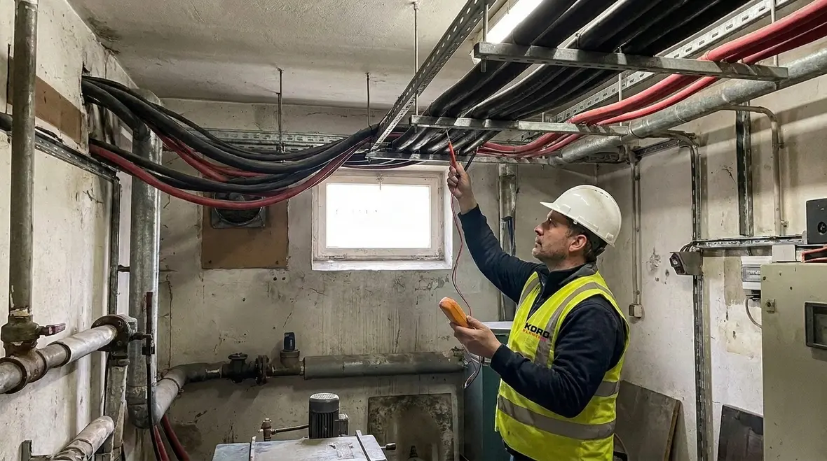
NFPA 70 Section 310.19 focuses on free air conditions and one key idea: how much current single insulated conductors can handle before insulation overheats. First, we make sure the conductor type matches the table assumptions, including insulation rating and size. Then we select the value that fits the job, not just the parts list. Finally, we document the reasoning so the design holds up when a reviewer asks, “How did you get there?”
Our expert service staff often explains it like this: the NEC tables are not a guess, they are a calculator that expects the right inputs. If the inputs change, the answer changes. So, before anyone claims a “magic ampacity,” we confirm the conditions that 310.19 assumes. That is where misunderstandings love to hide.
How engineers and electricians apply free air ampacity on commercial builds
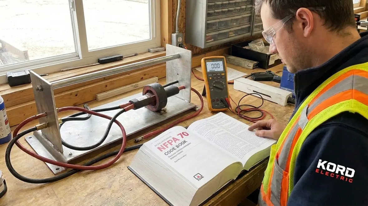
Commercial and industrial facilities do not operate like tidy classrooms. Loads move, rooms get reconfigured, and equipment adds up. Because of that, we treat 310.19 as the starting point, then we adjust using the rest of the NEC. In practice, our technicians review the full system: conductor length, termination temperature ratings, ambient temperature, and how cables run through trays, conduits, and cable bundles. After that, we compare the chosen conductor to the actual expected load.
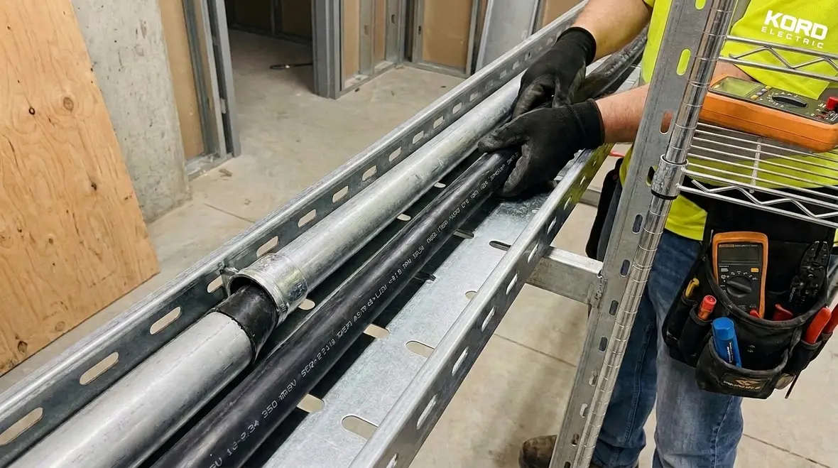
For example, if a feeder enters a switchboard and then branches into multiple circuits, the “free air” assumption may only apply at certain segments. Thus, we look at where the cable truly sits during operation. If it runs in a crowded tray, the derating factors and adjustment rules can reduce usable ampacity. We do not ignore that, because inspection teams do not either.
On larger projects, we connect these decisions with broader NEC guidance. For those who want the bigger picture on how NFPA 70 shapes modern installations, our article “Understanding NFPA 70: The National Electrical Code Explained for 2026” walks through how the code supports safer electrical system planning.
What “single insulated” really means in ampacity decisions
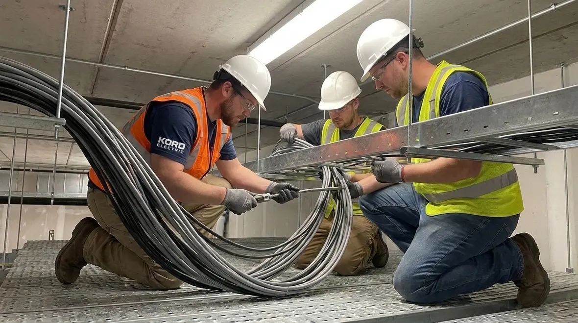
People hear “single conductor” and think it is always the same thing. However, the NEC wording matters. NFPA 70 310.19 addresses single insulated conductors, and that means the conductor is insulated as one unit, and ampacity tables reflect free air behavior for that setup. So, when our technicians evaluate a pull, they confirm conductor construction, insulation class, and installation details.
Also, we keep an eye on conductors that share a raceway or sit close together. When conductors are bundled or grouped, heat builds differently. Consequently, the ampacity from free air does not always transfer 1:1 to installed reality. Then, on industrial sites where cable trays run beside control wiring, we separate the decision from the wiring layout. In short: we size for the scenario, not for the brochure.
And if you are wondering whether electricians ever joke about this, yes. Someone once said derating rules “feel like taxes.” Our team responded, calmly, that at least taxes do not spark. Then we got back to the work.
Installation details that shift from table values to field reality
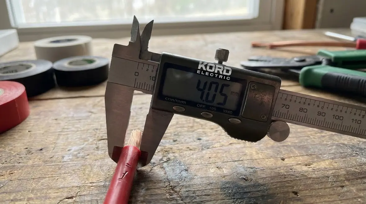
Once the design team pulls the correct ampacity from NEC free air single insulated ampacity rules, the job still needs a reality check. First, we verify the conductor insulation rating matches the intended use. Next, we check ambient temperature conditions in the exact location of the conductor. Then we consider the installation method, because raceways, cable trays, and conduit fill can change heat dissipation.
Additionally, we confirm where conductors route around hot equipment. In pump rooms, generator areas, and transformer spaces, temperature is not a theoretical number. It changes with runtime and with airflow. As a result, we apply the NEC adjustments that fit the scenario and we avoid shortcuts that lead to oversizing or, worse, undersizing.
For sites that also plan fire pump systems, we align electrical conductor decisions with life safety needs. Many of our clients work with standards and guidance tied to fire protection planning, and we coordinate with the electrical and life safety scope so the final installation stays compliant. When teams want a broader fire protection view of NFPA 70 and related standards, our partners at Kord Fire explain how the National Electrical Code links to wider fire and life safety planning.
Where technicians explain the “why” behind sizing choices
At Kord Electric, we do not just hand over a calculated answer. We teach the reasoning so facility managers and project stakeholders understand what they are buying. Our technicians and expert service staff explain the chain from NFPA 70 Section 310.19 through installation adjustments, so everyone sees how safety margins come from correct assumptions.
For example, we explain that free air ampacity establishes the ceiling under ideal heat conditions. Then, we explain how installation and environment reduce that ceiling. Finally, we show how that impacts breaker coordination, voltage drop planning, and the ability of equipment to start and run as expected.
This matters for major property buildings and industrial facilities, where one wrong sizing choice can cause recurring nuisance issues or reduce equipment life. And yes, those problems can look small at first, like a circuit that trips “sometimes.” But sometimes is how electrical failures build a fan club.
Compliance and documentation for commercial and industrial projects
Compliance is not a last minute activity. We build it in from the design and review stage, then we carry it through to installation verification. Our process considers code requirements tied to conductor ampacity, termination, and the way the wiring gets supported and routed. Then we verify that the final installed setup matches the design basis used to select conductors.
We also keep the project focused on the right audience. Kord Electric targets commercial and industrial facilities and major property buildings. So we prioritize documentation that these projects need, including clear sizing logic and practical installation notes that help contractors execute correctly.
If you want a broader look at how the NEC is explained for modern builds, our related resources discuss the NEC approach for 2026 updates and how to interpret the National Electrical Code in a way that supports safer designs. For reference materials on the code and how it applies, you can also explore our Kord Electric blog and Kord Fire resources.
Note for readers: Fire code planning and electrical code requirements often intersect. If a project includes life safety or fire pump systems, we coordinate the electrical scope in a way that supports the larger compliance picture, including guidance from groups like firepumps.org where applicable to industry context.
NEC free air single insulated ampacity in one practical workflow
When our team sizes a conductor for a commercial or industrial project, we use a workflow that stays consistent from job to job. That reduces mistakes and makes inspections easier.
- We identify the conductor size, insulation type, and operating scenario
- We pull the starting value for NEC free air single insulated ampacity based on NFPA 70 Section 310.19
- We apply the correct installation and environment adjustments so the final ampacity matches the field conditions
- We verify terminals, temperature limitations, and routing method
- We document the logic and confirm it fits the project’s electrical layout and load plan
This workflow is simple in theory, and solid in practice. Then again, electricity rarely cares how simple it looks on paper, so our checks keep the system calm and compliant.
FAQ: NFPA 70 310.19 and conductor ampacity basics
Ready for code-aligned conductor sizing on your project?
If you manage a commercial or industrial facility, we can help you size and verify wiring with the correct NEC logic, starting from NFPA 70 Section 310.19 and then adjusting for real installation conditions. Our technicians and expert service staff explain the “why” as they go, so the team understands the design, not just the numbers.
For projects in Southern California and beyond, our Los Angeles County electrical services support commercial and industrial facilities that need inspection-ready installations, documented ampacity logic, and practical field coordination. Whether you are planning a new build, an upgrade, or a targeted repair, we align conductor sizing with the NEC and the real behavior of your loads.
Contact Kord Electric to review your conductor plan, answer code questions, and keep your electrical system safe, stable, and inspection-ready.