NFPA 70 Section 310.17 single insulated free air ampacity
NFPA 70 Section 310.17 explained for commercial and industrial teams
At Kord Electric, we often see facilities treat NEC single-insulated free air ampacity like a single number that works for every job. It does not. In NFPA 70 Section 310.17, the rules for single insulated conductor ampacity in free air set the starting point for how much current a conductor can carry when it is not bundled, not buried, and not trapped under heat. Others guess, some “eyeball it,” and then the electrical room pays the bill. We prefer a calmer path. Our technicians and expert service staff explain this standard step by step, so your design and your maintenance choices match the code, not luck.
In this article, we walk through what Section 310.17 really means, why the free air condition matters, and how you use the table without accidentally skipping the parts that actually control the result.
Why free air ampacity tables matter more than people admit
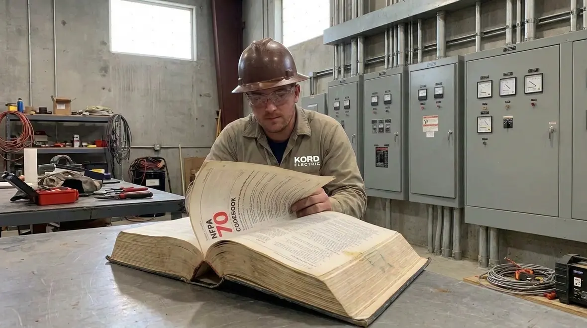
When power systems heat up, insulation ages faster. Therefore, ampacity rules exist to keep conductors in safe temperature limits. However, “safe” depends on the installation environment. That is why NEC single-insulated free air ampacity sits at the foundation. It answers one core question: if a conductor is in free air, with normal cooling, what current can it carry?
Now here is where teams slip. They treat free air as if it is installed everywhere. Yet in commercial and industrial facilities, conductors often sit in raceways, trays, cable systems, or near other conductors. So even when the sizing starts with Section 310.17, you still need to apply the adjustment factors and related rules that reflect real heat conditions.
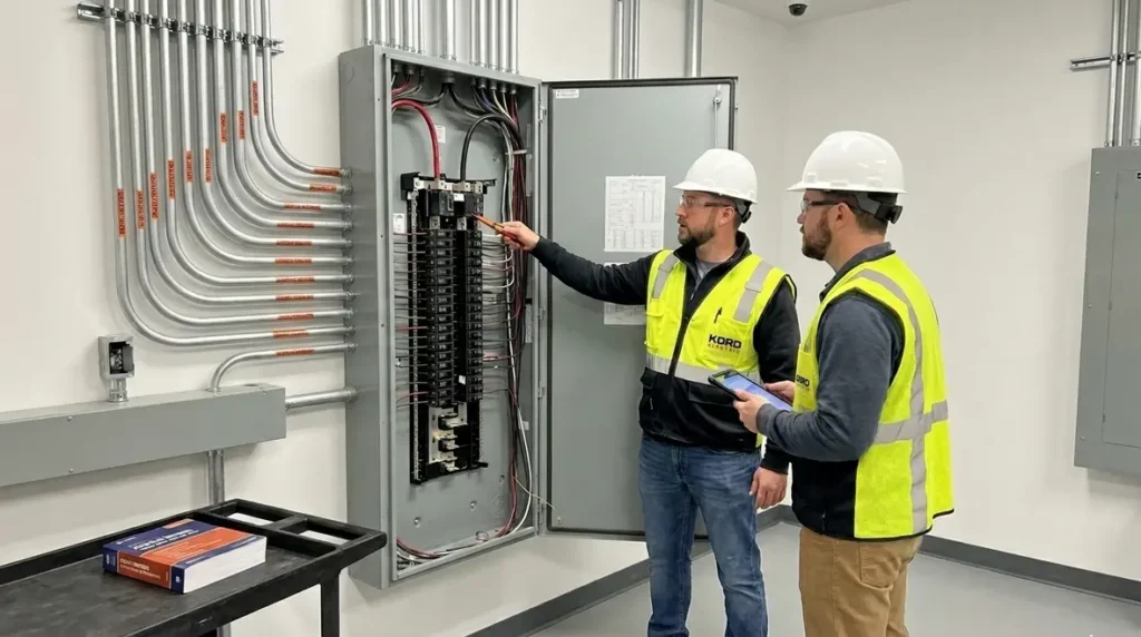
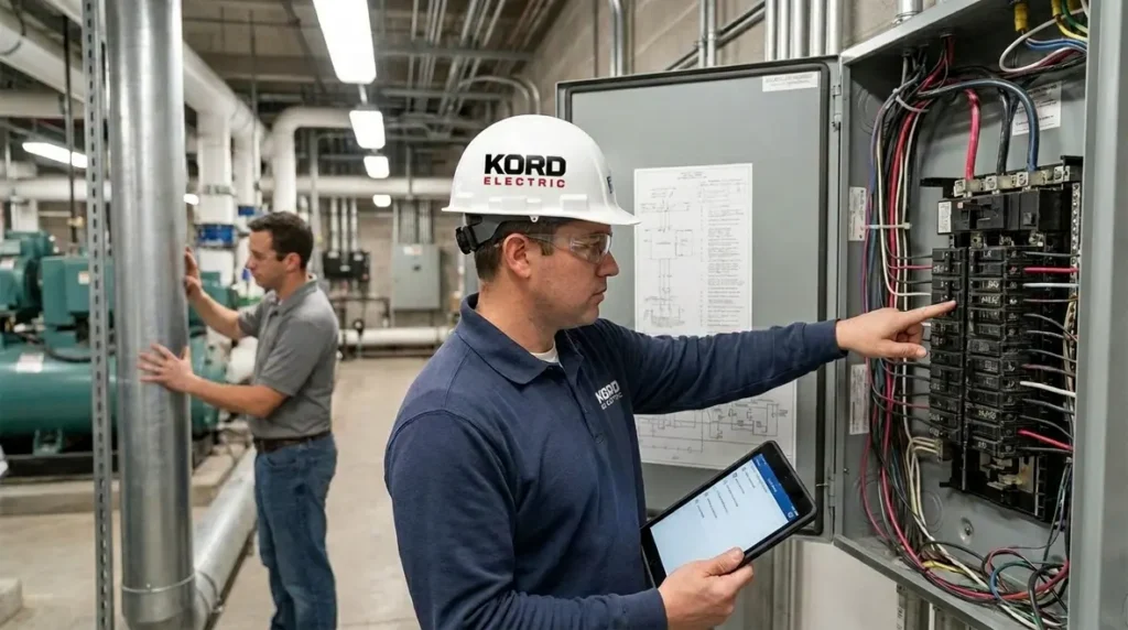
Our service staff explains it in plain terms during walk downs. They do not just say “use the table.” They show what changes when conductors share space, run in bundles, or sit in locations where heat builds up. That is the difference between a design that passes review and one that stays reliable for years.
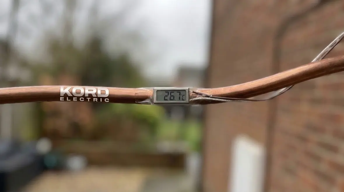
What NFPA 70 Section 310.17 actually sets up
Section 310.17 provides ampacity values for conductors with single insulation that are in free air. In other words, the table assumes air can circulate around the conductor and cool it. Since cooling drives temperature rise, these values become the baseline.
In practice, we tell our commercial and industrial clients to treat this baseline like the “ground floor” of the sizing process. From there, you adjust based on how the conductors sit and what else sits near them. For example, conductor bundling reduces heat escape. In addition, the insulation rating and ambient temperature influence the temperature the conductor actually experiences.
Also, remember that ampacity tables are not a license to ignore the rest of the NEC. The standard coordinates with other sections that address conductor types, temperature ratings, adjustment factors, and installation methods. If you skip a step, the final result can be wrong even if the first lookup looked correct.
For teams that want to connect these ampacity details to the broader rulebook, Kord Electric’s deeper primer Understanding NFPA 70: The National Electrical Code Explained For 2026 walks through how the NEC shapes real-world design and inspection expectations across commercial and industrial facilities.
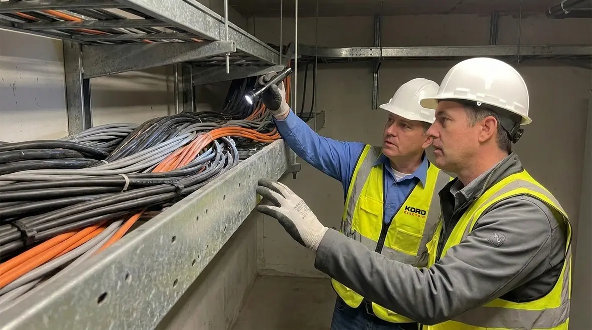
How we interpret single insulated conductor ampacity in real designs
In commercial and industrial projects, we support electrical design, upgrades, and maintenance work where load safety matters. That includes property types where reliability is not optional, and a “close enough” sizing approach can cause nuisance alarms, voltage drop issues, or worse.
Here is how our technicians and expert service staff explain the method, in a way that stays consistent across teams:
- Step one, confirm the conductor premise: we verify that the conductor insulation type aligns with the conditions described for single insulated free air ampacity
- Step two, determine the baseline current: we read the table for the conductor size and insulation rating at the assumed baseline condition
- Step three, apply adjustments: we account for how the conductors actually install, including how many conductors share the space and the installation environment
- Step four, cross-check system needs: we match ampacity choices to protection and operational requirements, because ampacity and device ratings must work together
And yes, we have seen designers who read the table like it is a fortune cookie. The table might say “you will have a safe conductor,” but only after you follow through with the adjustments. The code does not do drama. It does math.
Where adjustment factors and installation conditions change the outcome
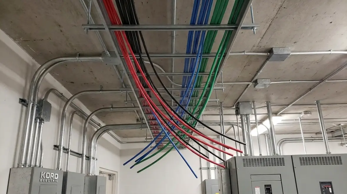
After the baseline, installation details steer the final ampacity. In busy electrical rooms, conductors often run in trays, share pathways, or sit in spaces with higher ambient temperature. Therefore, the real operating temperature can rise beyond what free air assumes.
So when our team works on commercial and industrial facilities, we pay attention to the conductor grouping reality. We ask how many conductors share the cable path, how heat dissipates in that corridor, and whether the installation method affects cooling. Then we apply the correct NEC adjustment rules that follow from the premise of the table.
We also help teams avoid one common trap. Some people look at free air ampacity and stop. Then they size raceway space later, as if routing choices do not change the electrical limits. However, the routing choice often locks in thermal behavior. In that sense, ampacity is not just about wire size. It is about the system you build around it.
Steel and smoke stories: thermal risk in fire and critical systems
For some facilities, the electrical system lives next to life safety equipment. That includes fire pump rooms, emergency circuits, and detection and control panels. We reference trusted industry guidance when we explain NEC concepts for life safety adjacent design, and we also coordinate with specialists who care about that work daily, including experts who focus on fire protection practices.
For teams in this space, the practical takeaway is simple. If thermal conditions reduce usable ampacity, the conductor can run hotter than expected. As temperature rises, insulation can degrade faster, and performance can shift over time. That risk is not theoretical. It shows up as recurring maintenance calls, equipment nuisance behavior, and premature component aging.
We often mention resources from the broader NEC education ecosystem, including guidance from sites like kordelectric.com and kordfire.com that help teams stay grounded in how the NEC explains installation intent. We also stay mindful of fire protection community resources, such as firepumps.org, because electrical reliability and fire safety planning frequently overlap in major property buildings.
So yes, we keep the tone professional. But we also keep it real. Electrical work that ignores thermal limits is like a smoke detector with the battery removed. You might feel brave, but you are not protected.
Two-column quick check: from table lookup to safe ampacity target
Below is a quick, non exhaustive flow our team uses to keep commercial and industrial projects aligned with the code intent. It is not a substitute for engineering judgment, but it helps teams avoid missing critical steps.
|
What you start with
|
What you must finish with
|
Common mistakes we see on commercial and industrial jobs
Even careful teams can trip on details. However, if you catch these issues early, you prevent costly rework and avoid system risks.
- Using free air values as final ampacity: this ignores thermal adjustment requirements driven by installation conditions
- Mixing conductor insulation assumptions: single insulated conductor conditions must match what the table supports
- Skipping conductor grouping reality: bundling and tray fill can change allowable current even if the wire size stays the same
- Overlooking ambient temperature effects: higher ambient conditions reduce usable ampacity relative to the baseline
- Not coordinating with protection devices: ampacity and overcurrent protection must work together for safe operation
Our technicians explain these points during pre start reviews and upgrade inspections. And if you think “we will catch it later,” we politely remind you that later is where budgets go to vacation and never return.
FAQ
Conclusion and next step with Kord Electric
Free air ampacity looks simple, but NEC single-insulated free air ampacity values become truly useful only when you apply the installation reality around them. We help commercial and industrial facilities get it right by walking through the table baseline, confirming conditions, and coordinating the result with protection and system needs.
If you are sizing conductors, planning an upgrade, or auditing an electrical system, Kord Electric’s team can also connect your project-level decisions to broader compliance and modernization goals. Resources across the Kord Electric blog, including guides on working space clearances, connection quality, and NFPA 70 strategy, support the same grounded approach you see in this Section 310.17 discussion.
For facilities in jurisdictions with detailed plan review expectations, including those similar to Los Angeles County electrical services requirements, that kind of coordination matters. Our technicians and expert service staff help you interpret the NEC, document the design, and install systems that meet both the letter and the intent of the rules.
If you are sizing conductors, planning an upgrade, or auditing an electrical system, contact Kord Electric. We will bring calm, code aligned clarity to your electrical decisions, one conductor at a time.