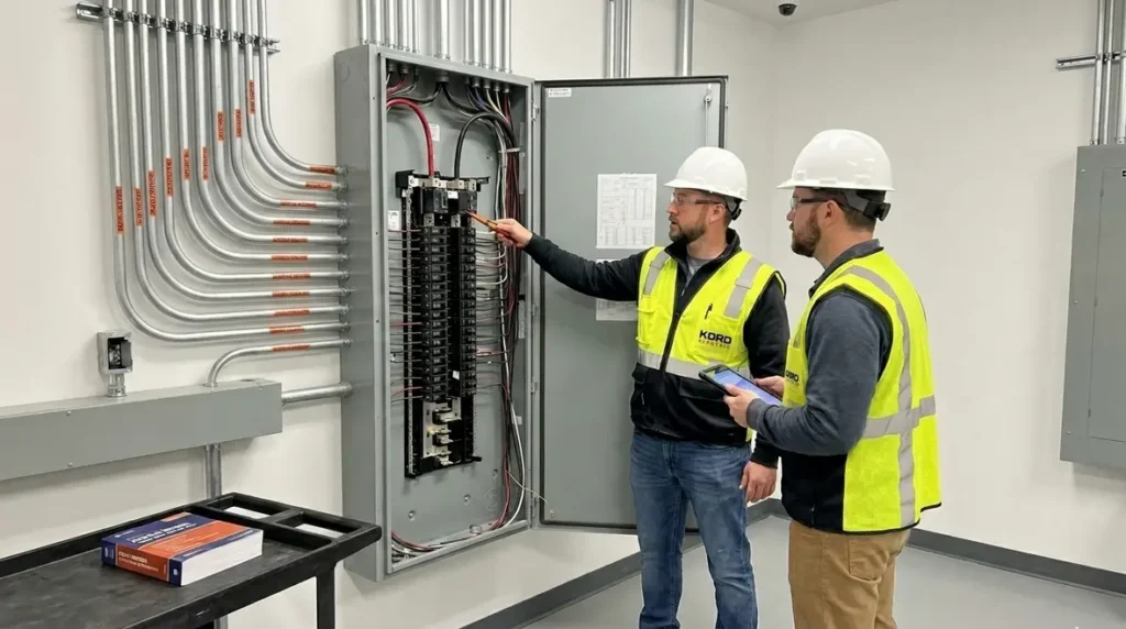
NEC ampacity tables guide for Section 310.15 safer load sizing
NEC ampacity tables guide: start here for safer load sizing in Section 310.15
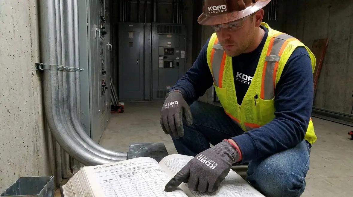
At Kord Electric, we treat NEC ampacity tables guide reading like a job skill, not a guessing game. When our technicians open the cover of the National Electrical Code, they do not look for magic numbers. They look for the right conductor size and the right conditions so current stays within safe limits. And yes, we’ve seen what happens when someone reads an ampacity table like it is a menu and not a rulebook. It never ends well. This article walks through how to read NFPA 70 Section 310.15 in a calm, practical way for commercial and industrial facilities, so electrical planners and property teams can size conductors with confidence.
Because NEC ampacity tables sit inside the wider code framework, our technicians also connect this topic with other resources on our blog. For example, Kord Electric’s guide Understanding NFPA 70: The National Electrical Code Explained for 2026 gives commercial and industrial teams a bigger-picture view of how conductor sizing, overcurrent protection, and load planning all fit together in the 2026 NEC landscape. When you pair that overview with this focused NEC ampacity tables guide, Section 310.15 stops feeling like isolated numbers and starts reading like part of a consistent safety story.
What Section 310.15 really does for conductor ampacity

In plain terms, NFPA 70 Section 310.15 helps determine the maximum allowable ampacity of conductors. That matters because current does not care about our optimism, and insulation does not care about deadlines. Therefore, the code sets limits based on conductor type, insulation rating, temperature, and installation conditions.
Our expert service staff explains this clearly on site for major property buildings because the real world rarely matches the paper example. For example, raceways fill up, ambient heat rises, and wiring runs through tight spaces. As conditions change, so do the required adjustments.
So when you read Section 310.15, you are not just looking up a rating. Instead, you confirm that the conductor will stay safe under the exact installation method and temperature factors that apply to your facility. In other words, you build a solution that can pass inspection and still make sense six months after the new equipment starts running.
We also see Section 310.15 as a bridge between day-one design and long term operation. When combined with NEC sections that govern feeders, branch circuits, and specific purpose loads, it helps prevent the two extremes facility teams worry about most: undersized conductors that overheat and oversized conductors that blow up budgets without adding real safety value.
Step by step: locate the right table before you trust any number
To read the NEC ampacity tables correctly, we start with location and intent. Section 310.15 uses ampacity tables that depend on the insulation and the conductor material. Then, the installation type and temperature rating affect which values you can use without adjustment.
Here is the method our technicians use, and it keeps teams from mixing apples with engine parts.
- First, identify the conductor material, like copper or aluminum.
- Next, confirm the insulation type and temperature rating that matches the job specifications.
- Then, choose the installation context that fits the wiring method used on your commercial or industrial project.
- After that, read the base ampacity value from the correct column in the NEC ampacity tables guide reference.
- Finally, apply any adjustment factors required by the conditions you actually have.
To be clear, we do not tell teams to “just pick the closest size.” Instead, we help them read the table for what it is: a baseline that still needs the right corrections.
If you want a structured way to practice this, you can pair this NEC ampacity tables guide with broader orientation pieces like Kord Electric’s article on how to read the National Electrical Code. Walking back and forth between high level navigation and detailed ampacity steps builds the kind of muscle memory that pays off during design reviews and inspections.
How temperature ratings and adjustment factors change the ampacity result
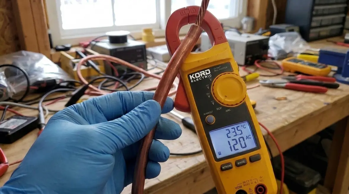
Conductors carry current, and current creates heat. Therefore, insulation temperature rating plays a direct role in how much current you can safely allow. If the surrounding environment or installation situation increases conductor temperature, the code requires adjustments.
Our team often sees this where facilities run long feeders through spaces with heat sources. In those cases, the conductor temperature rise can exceed what a simple table look up assumes.
Adjustment factors typically account for things like conductor insulation temperature rating, number of conductors in a raceway, and ambient temperature. As a result, the final allowable ampacity may be lower than the base value.
One of our expert service staff members likes to say, “A table value is like a first draft. It is useful, but it is not the final report.” He is right, and we back that up with field experience across commercial offices, warehouses, and industrial process areas.
When you apply these corrections, you are also supporting other NEC requirements that depend on correct current levels, such as feeder minimum rating rules, branch circuit behavior, and specific purpose load calculations. Getting the ampacity math right here keeps those other articles from becoming a string of unpleasant surprises when operating conditions change or new equipment gets added to the system.
Installation details that drive the NEC ampacity tables guide corrections
Section 310.15 does not live in a vacuum. It expects real installation details, and those details shape the correction steps. So even if two projects use the same wire size, the ampacity outcome can differ when the installation method differs.
For major property buildings and industrial sites, the common drivers include conduit fill, conductor grouping, burial depth where applicable, and the thermal environment around the wiring. Then there is the practical reality that cables do not run alone. They share space with other conductors, and that changes heat buildup.
To keep the process accurate, we advise facilities to document the installation method and verify the raceway and cable layout early. After all, a design that looks neat on paper can become a heat trap in the field. And nobody wants to discover that during commissioning, when the “quick fix” turns into a full redesign. That is the kind of plot twist nobody asked for, like a sitcom episode where the twist is you have been wrong since episode one.
This is also where cross-discipline planning helps. When electrical design teams coordinate with fire protection, life safety, and mechanical planners, you reduce the odds that a duct relocation, fire pump feeder, or new equipment pad quietly changes the thermal world your conductors live in. That coordination mindset shows up across Kord Electric and Kord Fire education materials, and it serves you just as well when you are in the weeds of Section 310.15.
Common reading mistakes and how our technicians prevent them
Even trained teams can stumble when they rush the table selection process. Therefore, we list the mistakes we commonly see, and we explain how to avoid them.
- Using the wrong insulation temperature rating. A conductor may look correct by size, but the insulation rating drives the allowable temperature limits.
- Ignoring grouping or conductor quantity. If more than one current carrying conductor shares the same raceway or cable, ampacity can drop.
- Skipping installation condition checks. If ambient temperature or heat sources differ from assumptions, the adjustment factors matter.
- Confusing base ampacity with adjusted ampacity. The table gives a starting point, not the final permission slip.
Our technicians prevent these errors by slowing down at the reading stage. Then, they confirm the input values and the installation facts before they finalize conductor sizing. In commercial and industrial work, that discipline reduces change orders, helps projects stay on schedule, and lowers the risk of failed inspections.
We also lean on structured documentation. By capturing which NEC ampacity tables guide entries were used, which adjustment factors were applied, and which assumptions were made about environment and grouping, facility teams build a trail that future inspectors, engineers, and maintenance staff can actually follow instead of guessing what “whoever did this last” meant at the time.
Dual column reality check: size conductors with the full method
When teams size conductors for commercial and industrial facilities, they should combine table selection with the required adjustments. To make the flow easy to review, we use a simple two track check. It is not complicated, but it keeps the logic clean.
|
Table selection
|
Adjustment and verification
|
Running this dual column reality check protects you on two fronts. First, it helps you avoid undersized conductors that cannot safely carry the calculated load. Second, it keeps you from overbuilding entire runs because someone misread a column heading or skipped an adjustment note. Over hundreds of feet of conduit and cable, that balance makes a real difference in both safety and cost.
FAQs about NFPA 70 Section 310.15 and conductor ampacity
Conclusion: let Kord Electric help you size conductors the right way
Reading NFPA 70 Section 310.15 should feel steady, not stressful. At Kord Electric, we help commercial and industrial facilities apply the right table values, then adjust them to match the installation conditions. Our technicians and expert service staff walk teams through the process, explain the why behind each step, and support clean documentation for inspections. If you are planning new service, major upgrades, or rework that affects conductor sizing, contact us now. We will help you land the design safely, on time, and without the “surprise, it fails” moment.
As projects grow, this NEC ampacity tables guide becomes even more powerful when you connect it with other planning tools. Facility teams in Los Angeles County and surrounding regions often combine our Section 310.15 conductor sizing support with broader Los Angeles County electrical services from Kord Electric, so load calculations, feeder routing, and protective device selection all line up under the same NEC strategy. That whole-system view keeps your upgrades from turning into a patchwork of one-off fixes.
If you want more background on how Section 310.15 fits into the rest of NFPA 70, you can explore resources like Kord Electric’s 2026 National Electrical Code explainers or Kord Fire’s NEC-focused coverage. Pairing those high level views with this focused NEC ampacity tables guide gives your team a shared language for safe conductor sizing, safer load planning, and better coordination with fire and life safety systems across your building.