NEC MC Cable Splices Taps NFPA 70 322 56 Meaning
NEC MC cable splices and taps: what NFPA 70 Section 322.56 really means
In commercial and industrial buildings, our work at Kord Electric often comes down to one question: how do you connect NEC MC cable safely when a run needs to change direction, pass through a box, or feed new equipment. That is where NFPA 70 Section 322.56 enters the picture, especially for NEC MC cable splices taps in Metal Clad cable. We explain it in plain terms because the code should not feel like a puzzle box. And yes, sometimes people treat splices like party favors, tossing them together and hoping nobody checks. That is not how electricity behaves, and it is not how we work.
Our expert service staff and technicians walk job sites every day, so we see what corners get cut and what paperwork gets ignored. Then we fix it, document it, and move on with confidence. Next, we break down what Section 322.56 demands, what good installs look like, and how to plan connections without risking failures, fire damage, or downtime.
NFPA 70 322.56 in plain language for field teams
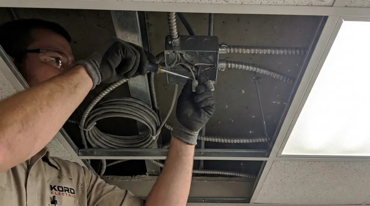
NFPA 70 Section 322.56 covers how you handle splices and taps in MC cable. In practice, it tells you the rules for making connections while maintaining safe insulation, proper enclosure, and correct electrical continuity. Put simply, the section exists because a splice is not “just a splice.” It can become the weak link if the installer uses the wrong method, the wrong connector, or the wrong location.
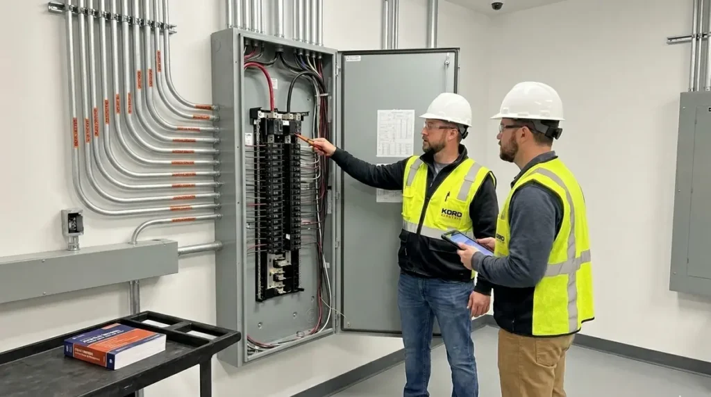
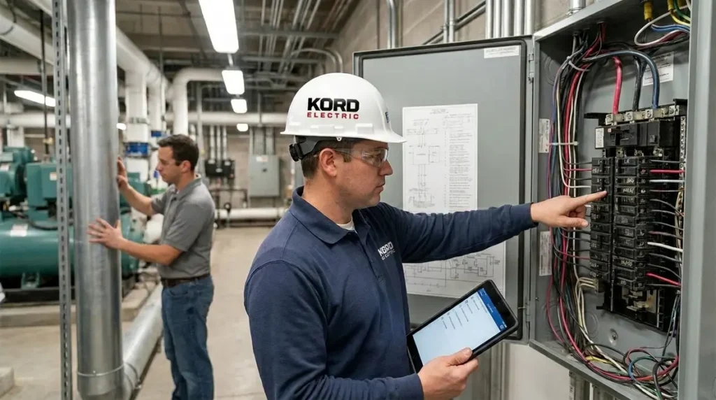
So, when our team reviews designs and then verifies installs, we look at the entire chain: the cable type, the connector rating, the box or enclosure, and the termination approach. Additionally, we check that the splice method matches what the code allows for the cable system. In our experience, teams avoid trouble when they treat 322.56 like a recipe, not a suggestion.
We also remind managers that code compliance is not only about passing an inspection. It is about reducing long term maintenance calls. That is how a commercial facility stays online, and that is how we help property teams protect investment value. When teams want a deeper dive into the bigger rulebook behind these requirements, we often point them to our explainer Understanding NFPA 70: The National Electrical Code Explained for 2026, which connects everyday field decisions back to core NEC guidance.
Where splices belong and how boxes stay compliant
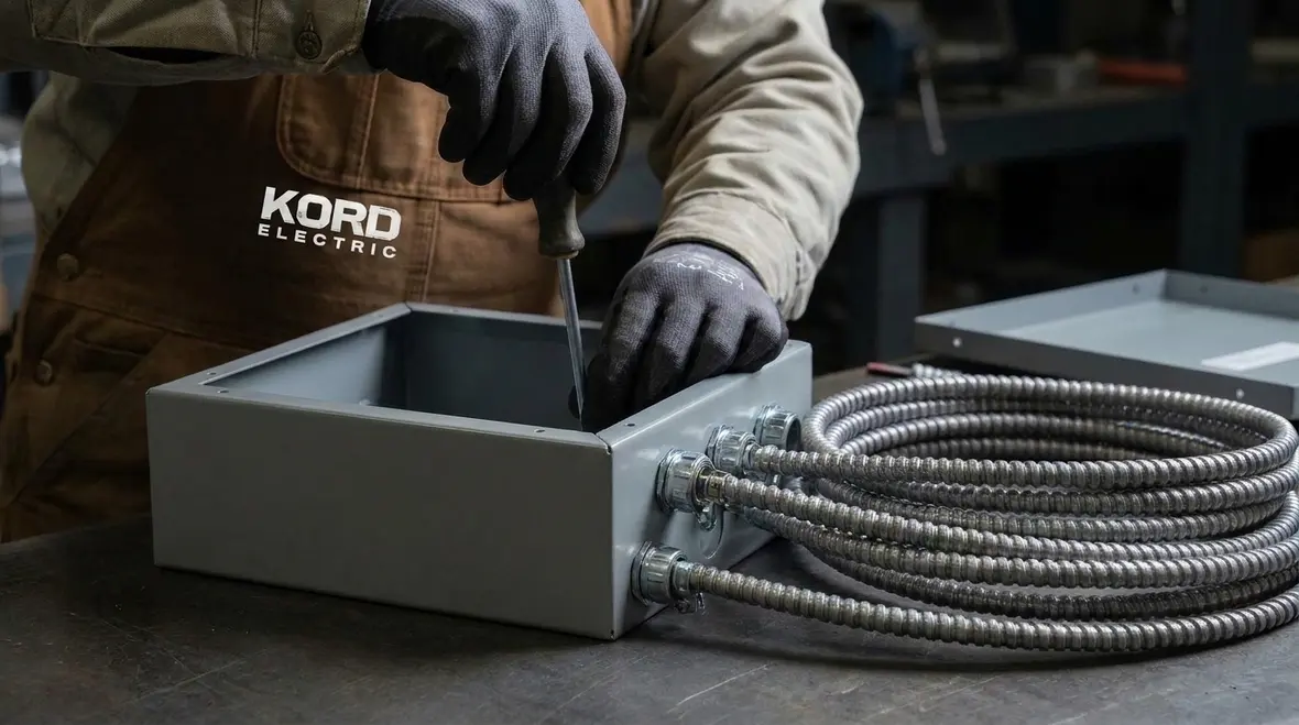
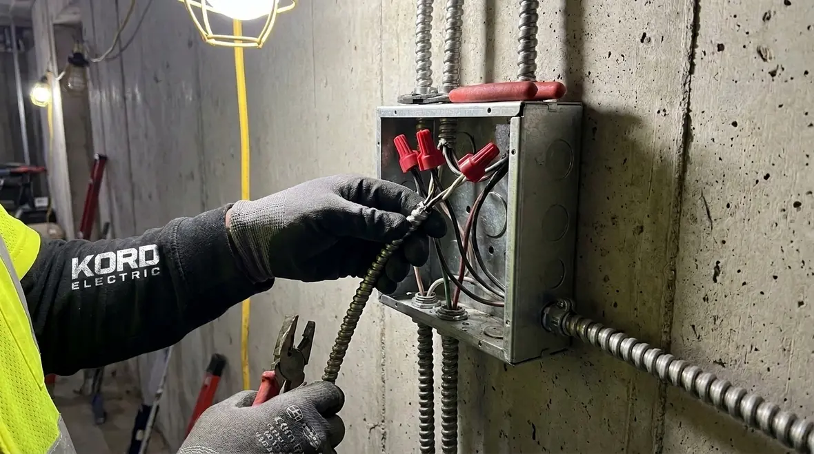
When people hear “splice location,” they often imagine a hidden junction inside the wall. However, Section 322.56 pushes installers toward using appropriate enclosures. We do this for a reason: a splice needs protection from physical damage and moisture intrusion based on the installation environment. In commercial and industrial spaces, cable runs frequently move through varied zones, so our technicians plan splice locations before they open a single ceiling tile.
Common field mistakes include using an enclosure that is too small, leaving conductors under strain, or installing connectors that do not match the box and cable requirements. Therefore, our process includes verifying the box fill, connector compatibility, and whether the enclosure supports the required protection. If the site uses pull sections, access panels, or equipment areas, we place splice access where maintenance teams can reach it without demolition.
And just to keep it real, our techs sometimes hear jokes like “if it works today, it works tomorrow.” Electricity does not care about tomorrow’s humor. It cares about insulation integrity, secure connections, and correct enclosure practices.
Approved connector choices that prevent heat and failure
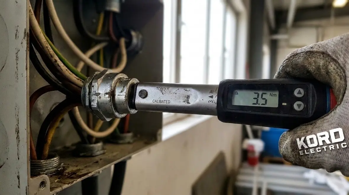
Next, we focus on the connection method itself. For MC cable connections, safe performance depends on components that fit the job. Section 322.56 aligns splices and taps with approved practices, which means the connector or splicing device must be suitable for the cable conductors, the insulation type, and the environment. When our technicians explain this to facility managers, they often compare it to plumbing: if the connector does not match the pipe, you get leaks. In electrical work, the visible leak might not show up right away, but the heat signature can tell the story.
Our expert service staff verifies that the splice method preserves conductor insulation and provides a durable electrical connection. We also check workmanship details such as conductor prep, torque values when required, and whether the installer maintains conductor spacing inside the enclosure. Even small errors can create stress points where heat builds over time.
Then we apply continuity and insulation testing where required by the project scope and standards. That step matters because it confirms the install meets the expected electrical condition, not only the appearance of the work.
Understanding taps on MC cable without guessing
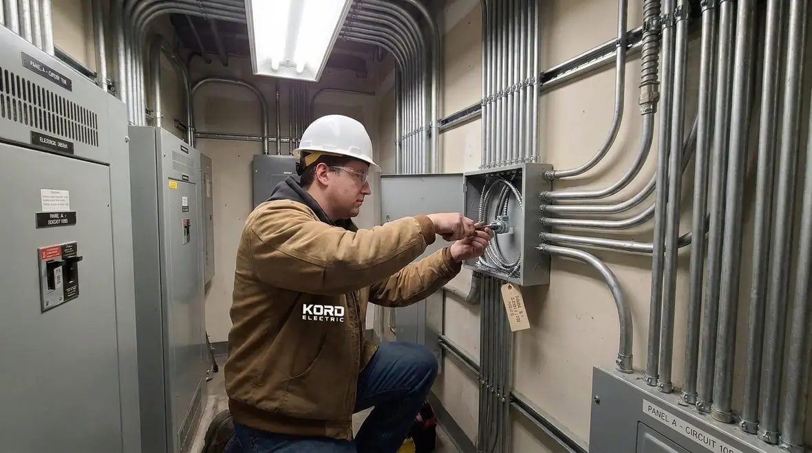
Taps deserve special attention because they can tempt crews into “quick connections.” Yet in commercial systems, taps must follow the rules of Section 322.56 and the broader NEC requirements that govern cable derating, conductor sizing, and safe current handling. In simple terms, a tap changes how the circuit distributes power. Therefore, the tap method must keep the system safe under load.
Our team helps projects avoid guesswork by treating tap design as part of engineering, not part of improvisation. We coordinate tap locations with equipment loads, conduit routing, and access for future service. Additionally, we review whether the tap method and enclosure match the installation conditions.
If you have ever watched a maintenance tech chase a recurring nuisance shutdown, you know how expensive “close enough” becomes. A tap that is poorly designed can contribute to voltage drop, overheating, or intermittent faults. So we plan, we document, and we install with care. That is how facilities stay stable, and that is how we earn long term trust.
How we document compliance for commercial inspections
Because our clients build and operate high value spaces, we treat documentation as a core part of the electrical system. After all, inspectors and facility engineers want clear evidence that the installation follows the NEC and the project’s approved design. As a result, NEC MC cable splices taps work gets tracked, labeled, and checked in a way that reduces rework.
Our technicians often use a simple approach during installation: verify first, install second, test third, then document. We also coordinate with general contractors so access panels and enclosure locations remain accessible. Then, during closeout, we provide records that help operations teams manage maintenance schedules.
Where our process stands out is the calm, thorough communication. Our expert service staff explains the “why” behind each rule. That way, managers and facility leads understand what they can expect during maintenance and why certain enclosures require access. We do not hide behind buzzwords. We explain like people, because that is the only way compliance becomes real.
Quick comparisons: splices versus taps in the field
It helps to keep the difference clear on site. While both involve connecting conductors, splices generally connect conductors to continue a run or extend a circuit pathway. Taps branch power from an existing cable to feed a device or load. Even though the two tasks can happen in similar locations, they behave differently in terms of how engineers plan current flow and how installers manage connection details.
To keep projects organized, our crews often follow a checklist during rough in and trim out. For example, we confirm conductor identity, ensure the correct connector is used, verify the enclosure placement, and confirm that the installation maintains proper protection. Then, if the job requires it, we conduct testing and record results.
And yes, we still laugh when someone asks if a splice can be “hidden better.” We tell them hiding mistakes never helps. It just helps them age like a fine wine, except the bouquet is smoke and the vintage date is failure.
FAQ about NFPA 70 Section 322.56 and MC cable connections
Planning NEC MC cable splices and taps into your broader electrical strategy
Splices and taps do not live in a vacuum. Every decision you make about where to interrupt or branch MC cable interacts with the rest of your electrical strategy: panel loading, selective coordination, surge protection, and even future renovation plans. That is why our crews do not treat NEC MC cable splices taps usage as an isolated task. We fold it into how the entire system will behave during normal operation and during faults.
On many projects, that means taking a step back before anyone opens a junction box. We review single line diagrams, panel schedules, and mechanical coordination points. Then we decide where splices and taps make the most sense for present loads and likely changes. This approach also reduces the number of “mystery junctions” that haunt facilities years later, when nobody remembers why a certain box exists or what it feeds.
When MC cable work ties into larger electrical upgrades or lifecycle planning, our team often coordinates it with broader initiatives like infrastructure modernization, surge protection improvements, and code-driven renovations. That way, the effort you invest in clean, compliant splices and taps does double duty: it keeps today’s circuits healthy and supports tomorrow’s projects without rework.
For facility leaders planning more comprehensive changes, our dedicated consulting and project teams help translate NEC language into actionable scope. Whether you are coordinating tenant improvements across multiple floors or preparing for a major equipment rollout, we align MC cable details with everything else happening in your electrical rooms and above your ceilings.
Because many of our commercial and industrial clients operate in and around Southern California, they also lean on us for region-specific support. From local adoption of NFPA 70 requirements to inspection preferences in Los Angeles County, we use day-to-day field experience to keep projects moving instead of getting stuck at the last-minute review stage. If your facility team wants hands-on help implementing the ideas in this article, our Los Angeles County electrical services offering is built precisely for that environment.
Conclusion: get MC cable connections right before problems get loud
At Kord Electric, we treat NFPA 70 Section 322.56 like a safety map, not a legal maze. Our technicians and expert service staff plan splice and tap locations, verify approved methods, and document the work so commercial inspections go smoother. If your facility has aging cable runs, new equipment feeds, or maintenance planned, we can help you design the right connection strategy and install it with care. Call us today so your electrical system stays stable, safe, and boring in the best way.
If you are also exploring larger code and infrastructure questions beyond MC cable, our team can connect this work to broader planning efforts, from electrical code upgrade consulting to long-range modernization roadmaps. That way, every splice and tap decision fits into a bigger story of safety, uptime, and smart capital spending rather than a patchwork of one-off fixes.