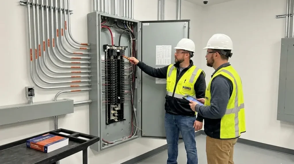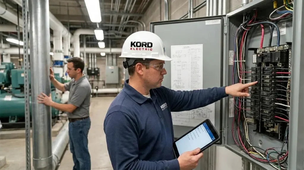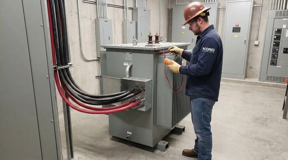
NEC Section 630.31 Welding Transformer Conductor Sizing
NEC Section 630.31 welding transformer conductor sizing matters the moment a facility plans a welding setup, because conductor size shapes voltage drop, safe heat rise, and long term reliability. In fact, when we help commercial and industrial sites, we often see the same pattern: someone picks a breaker first, then hopes the cables will “figure it out later.” They do not.
At Kord Electric, we support major property buildings with electrical work that stays compliant and stays practical. And while the name “NEC” can sound like homework, our technicians and expert service staff break it down step by step, so your team knows what we’re doing, why we’re doing it, and what you gain by doing it right.
So in this article, we explain how NEC rules connect to real job planning, with a calm, clear path from transformer to conductors to inspections. Yes, it can be as riveting as a welding arc, minus the sunglasses.
NEC basics for welding systems in commercial and industrial spaces
To size conductors correctly, we start with the National Electrical Code framework used for electrical design. In North America, that code guides how systems handle current, heat, and insulation life. For welding transformer circuits, the risk is not just a code issue. It is a practical issue that affects uptime, maintenance costs, and safety.
First, welding loads are not always steady like HVAC. They can cycle, and current can change during operation. Then again, the transformer behaves differently than a simple motor or lighting circuit. This is why we treat the welding transformer conductor job like a system, not a guessing game.
Meanwhile, Kord Electric works with commercial and industrial facilities and major property buildings, where documentation, coordination, and inspection readiness matter. In our expert service approach, we review the equipment ratings, the welding duty cycle, and how the building distribution system supports the load.
Our team then ties the wiring design to the relevant NEC requirements, including the parts that cover how conductors must be sized for welding transformer circuits. We also connect those decisions to broader NFPA 70 planning, often pointing facility teams to resources like our Kord Electric blog feature on Understanding NFPA 70: The National Electrical Code Explained for 2026 so they can see how individual sections sit inside the larger rulebook for safe electrical systems.
How NEC Section 630.31 drives correct conductor sizing
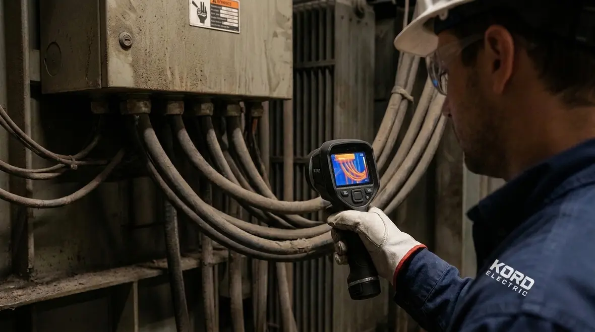
Now we get to the core: NEC Section 630.31 welding transformer conductor sizing. This rule gives direction for sizing the conductors that feed welding transformers. When people skip careful sizing, they often end up with voltage drop problems, nuisance shutdowns, or premature insulation wear. And if you think insulation failure will send an email before it happens, we have bad news. It usually does not.
In practice, we use the welding transformer nameplate data and installation conditions. Then we align the conductor sizing to the NEC approach for welding circuits. We also check how the conductors run through the building, because derating can come into play when temperature conditions or installation methods call for it.
Furthermore, we verify that conductor sizing supports safe performance under load. We also ensure the circuit protection scheme works with the conductor size and the welding transformer’s expected current profile.
Our technicians explain each step during planning and during installation. For example, if we need to adjust conductor size due to temperature or conduit fill, we walk your electrical manager through the reasoning, not just the result. That way, your team can approve the plan with confidence.
We map transformer data to conductor selection without shortcuts
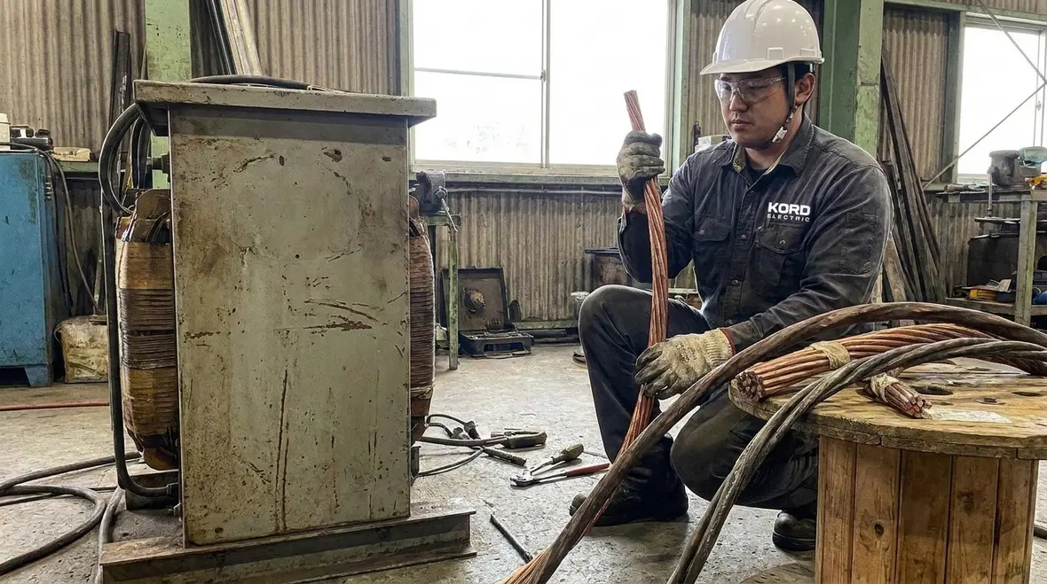
Next, we translate equipment information into a conductor plan. Welding transformers typically have data that points to primary current and secondary output characteristics. Although your operators might only “see” the output at the welding leads, your facility still depends on the upstream wiring to deliver power safely.
To do this well, we use a structured workflow. We start by confirming the transformer rating and application details. Then we confirm the feed conductor requirements based on NEC guidance, and we evaluate installation conditions such as conduit type, ambient temperature, and the number of current carrying conductors in a raceway.
At this stage, our expert service staff often catches planning gaps that others miss. For instance, a spec might list a transformer size but not confirm where the transformer will sit in the building relative to the main service and distribution panels. Therefore, conductor length and routing become part of the sizing and voltage drop checks.
We also coordinate with building stakeholders early. Since we focus on commercial and industrial facilities and major property buildings, we keep shutdown planning realistic and we document everything needed for compliance and inspection.
Think of it like a movie plot: if you ignore where the scene happens, the finale will not make sense. Electrical planning works the same way, except the villain is usually an undersized wire, and it does not wear a cape.
Voltage drop, heat rise, and why “close enough” fails
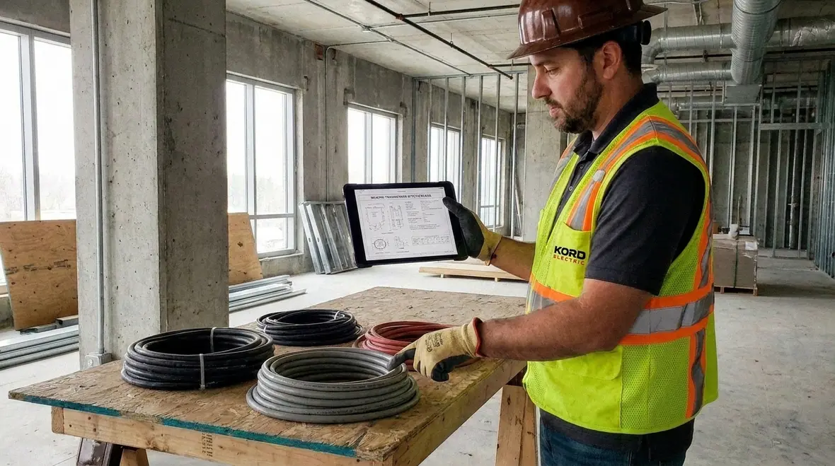
Even when a conductor meets a basic sizing target, the installation must still perform under real use. Welding circuits can impose loads that stress the system, which makes voltage drop and heat rise more than theory.
Here is how we handle it. First, we evaluate voltage drop along the run, especially when the transformer sits far from the distribution source. Then we consider heat rise, because conductor temperature influences insulation life and long term safety.
Moreover, conductor temperature affects how the wiring system ages. If a circuit runs hotter than expected due to installation conditions or conductor mismatch, you shorten the useful life. Over time, that can turn a planned maintenance cycle into a surprise emergency repair.
We also plan for how welding operations will behave. Some sites use welding in bursts with downtime between tasks. Other sites run welding as a more regular production activity. Since those realities change how the system performs, our approach reflects the facility’s operating pattern.
In short, we do not treat conductor sizing like a checkbox. We treat it like a performance requirement.
Installation coordination in large buildings and property complexes
After sizing comes the real world: routing, raceways, terminations, and coordination with other trades. In major property buildings, electrical work lives alongside fire alarm systems, life safety devices, HVAC, access control, and more. If we ignore coordination, the schedule gets messy, and the inspection package gets harder.
So we coordinate. Our technicians confirm conduit runs, verify space for raceways, and plan for proper bends and pulls. Then we check termination quality, because welding transformers ask a lot from connections that must stay tight and clean over time.
Also, we plan the protection scheme so it aligns with the conductor plan and transformer requirements. That alignment matters because protection that does not match the conductor design can lead to nuisance trips or unsafe conditions.
And if you wonder how this connects to fire and safety, it does. Electrical design and installation influence how the system behaves under fault conditions. For teams who want to align their electrical and fire safety thinking, we point stakeholders to resources like our sister brand sites at Kord Fire and our NEC-focused guidance at Kord Fire NEC guide, which helps building teams connect the dots between compliance and on site safety.
In the same spirit, organizations that support fire and safety education, like FirePumps.org, help broaden how teams think about system readiness. We keep our work focused on electrical systems for commercial and industrial facilities, but we always respect that safety is a whole building story, not a single panel.
Inspections, documentation, and keeping projects audit ready
When inspections happen, the code story must show up in the paperwork and in the installation. We help your team stay audit ready. That means we organize project documentation, including calculations, equipment cut sheets, and installation details tied to the approved design.
Because welding transformer circuits involve specific conductor sizing rules, we make sure the documentation clearly reflects the NEC requirements used for the design. Then we ensure the installation matches the plan in the field.
Our technicians also communicate the “why” during commissioning. They explain the sizing logic, the protection coordination, and any field decisions that could affect performance. If something changes due to routing constraints or material substitutions, we document those changes and confirm they remain compliant.
And yes, we do not want your facility dealing with a last minute scramble. In the real world, nobody loves a surprise inspection, especially when the electrical closet looks like a storage unit for forgotten parts from 1998.
FAQ about NEC welding transformer conductor sizing
Frequently asked questions for quick clarity
How do Kord Electric technicians handle sizing decisions?
We use transformer data, NEC welding circuit rules, and installation conditions, then we verify the plan supports safe performance.
Do you support major property buildings and industrial sites?
Yes. We focus on commercial and industrial facilities and major property buildings, with documentation and coordination built for inspections.
What should a facility provide to speed up design?
Transformer model details, expected welding load use, planned location, conduit route info, and any site temperature or raceway constraints.
Can installation changes affect compliance?
Yes. If routing, conductor type, or installation conditions change, we confirm the design still meets NEC requirements.
Why is documentation important for welding transformer circuits?
Because conductor sizing rules are specific. Good documentation helps inspections and reduces design risk during commissioning.
Conclusion and call to action
Welding transformer circuits deserve more than a quick cable choice. When you size conductors with NEC welding transformer conductor sizing in mind, you protect safety, reduce heat stress, and help your facility run without drama. At Kord Electric, our technicians explain the logic clearly and install with coordination for commercial and industrial facilities and major property buildings. If you are planning a new welding setup or upgrading an existing system, contact us for a compliant, inspection ready design and installation plan today.
For facilities across Southern California that want help applying NEC Section 630.31 welding transformer conductor sizing and related NFPA 70 requirements on real projects, our Los Angeles County electrical services team supports everything from planning and permitting to final inspections for commercial and industrial buildings.