NEC Section 690.8 PV Circuit Sizing for Compliant Solar
NEC Section 690.8 PV circuit sizing: the starting point for safe, compliant solar
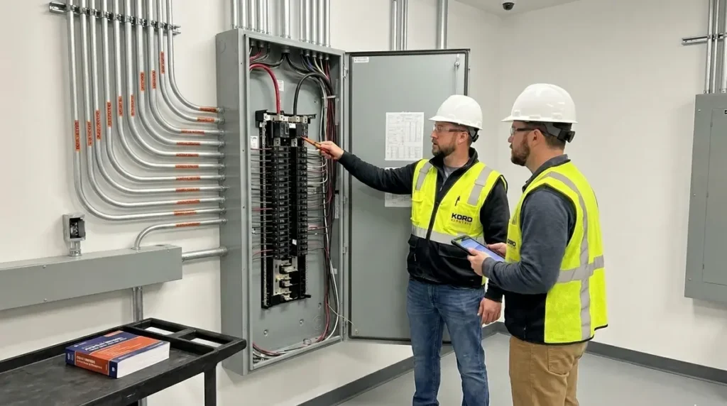
At Kord Electric, we guide commercial and industrial facilities through the electrical side of solar with a steady hand and clear documentation. In the first place, NEC Section 690.8 PV circuit sizing sets the rules for sizing PV source and output circuits, so systems carry current the right way and protective devices trip when they should. That matters most for major property buildings, where one bad design choice can ripple into service calls, delays, and expensive fixes. Meanwhile, our technicians explain the logic behind the code in plain terms, because reading a standard should feel less like punishment and more like instruction. We also know the jokes write themselves, because “size the circuit” sounds simple until you’re dealing with multiple strings, backfeed concerns, and real-world voltage drop.
Why the NEC treats PV like a system, not a pile of parts
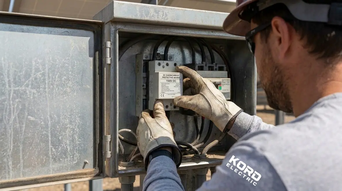
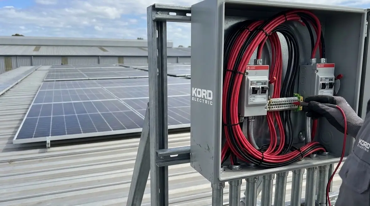
When people talk about solar, they often picture panels, inverters, and a nice view. However, NEC thinking works differently. The code treats the PV field, the conductors, the disconnects, and the overcurrent protection as one connected system that must behave under normal operation and fault conditions. As a result, we look at how modules connect to strings, how strings land on combiner equipment, and how the output path ties into the rest of the facility electrical gear.
In practice, our expert service staff step through the design flow with the project team. First, we confirm the electrical configuration, then we map the pathway of current, and finally we test whether the sizing rules line up with the protective devices and the equipment ratings. That is also why we reference the NEC approach described in our guidance at KordFire and Kord Electric, including the broader National Electrical Code framework described in resources such as Understanding NFPA 70: The National Electrical Code Explained for 2026. We keep it calm and deliberate, because the electrical code never “vibes.” It just requires.
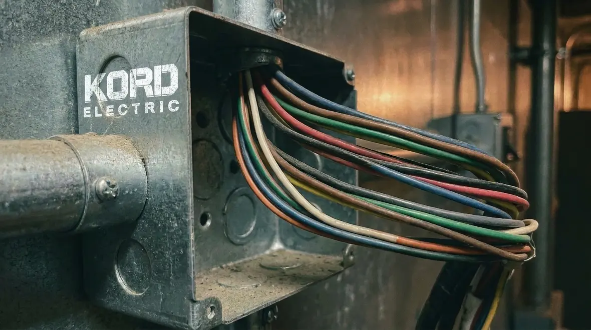
PV circuit conductors: current paths, temperature effects, and real voltage
Proper NEC Section 690.8 PV circuit sizing does not live in isolation. It starts with the current the PV system can produce, then it considers conductor behavior in the real world. Therefore, we evaluate conductor ampacity with the insulation rating, ambient temperature, and installation method. We also check whether derating applies, especially when circuits run through hot electrical rooms or in enclosed raceways.
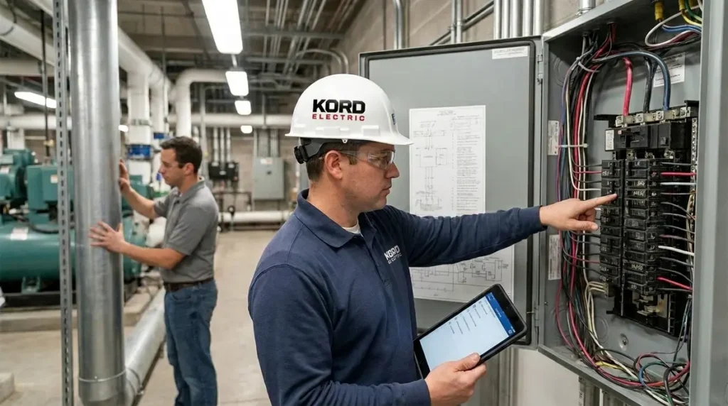
Next, we consider where the current goes. PV source circuits are not just “wires from A to B.” They carry maximum current under defined conditions, and they route through components that must coordinate. In commercial and industrial spaces, those routing decisions often intersect with equipment rooms, switchboards, and safety signage requirements. Then the electrician in charge has to make those choices hold up under inspection.
Our technicians explain it like this during walkthroughs. If the conductor is undersized, heat builds up, insulation ages faster, and voltage drop can climb until performance suffers. If the conductor is oversized without coordination, protective devices may not operate correctly. In other words, the system must balance capacity and protection. Like a good commercial relationship, it needs trust and clear boundaries.
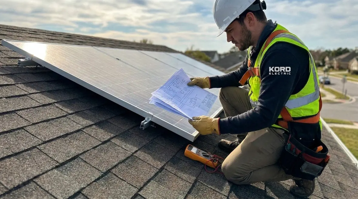
Overcurrent protection and coordination with PV outputs
After conductor sizing, we move to the next layer: how protection works. PV circuits include overcurrent protection requirements, and the design must align with what the protective devices can handle. In a facility, overcurrent devices must protect conductors and equipment while still allowing normal current to flow during sunshine, start up, and transient conditions.
We often see teams focus on panel output and inverter efficiency, then quietly hope the protection part sorts itself out. It does not. That hope is as reliable as a costume at a safety meeting. Our staff coordinate the circuit sizing approach with the protective device selection, ensuring the ratings and installation rules match the PV configuration.
To do this, we verify the maximum circuit current values, then we apply the NEC sizing method to ensure conductors, junctions, and disconnects can safely handle expected conditions. We also check coordination with the downstream distribution equipment so the entire pathway behaves predictably. This is where facility owners and general contractors appreciate the practical detail. We do not just quote code lines; we translate them into decisions that electricians can build and inspectors can verify.
Voltage drop, fault behavior, and why inspections look deeper than panels
In many major property projects, solar arrives with other electrical upgrades. That means designers must think about voltage drop, fault current contribution, and how faults may move energy through the system. Even when NEC Section 690.8 PV circuit sizing is correct, poor planning in routing or grounding can still create problems. We address this by treating sizing as one step in a broader electrical safety package.
For voltage drop, we review conductor length, circuit loading, and operating voltage. Then we check whether performance remains within acceptable limits for the inverter and connected equipment. Meanwhile, for fault behavior, we look at how PV circuits feed into protection and how equipment responds when something goes wrong. That includes how disconnects function during maintenance, and how labels and system diagrams match what field crews install.
Our team uses a methodical approach. First, we verify conductor data and installation conditions. Next, we cross check device ratings and coordination. Then, we document the calculation steps so the electrical contractor, facility engineer, and inspector all see the same story. If we were telling it as a movie, this would be the scene where everyone agrees on the plot before the credits roll.
How Kord Electric supports commercial and industrial solar projects end to end
Kord Electric supports commercial and industrial facilities and major property buildings. We do not chase random installs; we focus on projects where electrical design clarity and installation discipline matter. As we work with teams, we align with the NEC and related guidance from our fire and electrical resources, including the broader themes covered in KordFire content and the code focused training that fire safety stakeholders also rely on.
Our expert service staff help in the places that usually cause delays. We review design assumptions, validate circuit sizing logic, and confirm that equipment selections fit the real installation conditions. Then, we help coordinate field execution so wiring methods, conduit fills, and termination practices match what the calculations assume.
We also bring a practical mindset. If an engineer or electrical contractor asks a question, we answer directly and show how the code reasoning supports the answer. That way the project keeps moving. And yes, sometimes we explain things twice, because code compliance is not a “got it, move on” kind of subject. It is a “verify it and document it” kind of subject.
Table view: mapping PV sizing decisions to inspection realities
FAQ: NEC PV circuit sizing for commercial solar teams
Final word from Kord Electric
Solar projects succeed when sizing logic, protection coordination, and installation details align from day one. At Kord Electric, we support commercial and industrial facilities with careful review, clear explanations, and field guidance that keeps your project moving. If you want NEC focused PV circuit sizing done with confidence, bring your design documents and we will help you validate the plan before it turns into a costly surprise. Our Los Angeles County electrical services team can also coordinate PV-related work with broader facility upgrades so everything stays aligned with the NEC and local expectations.
Contact us now and let our technicians walk you through the details, calmly and clearly.