NFPA 70 270.148 NEC EGC Continuity 2 kV Box Attachment
NFPA 70 Section 270.148, EGC continuity, and 2 kV box attachment
At Kord Electric, we support commercial and industrial facilities and major property buildings with electrical systems that stay safe when the load gets real. In this guide, we focus on NFPA 70 Section 270.148, with special attention to the NEC EGC boxes 2 kV requirements for grounding and box attachment. In the first part, we explain why EGC continuity and secure attachment matter at the 2 kV level. Then, our trained technicians walk through practical steps we use on site, and we clarify how the rule affects testing and field decisions. Because in our world, the code is not trivia. It is the map that keeps people safe and keeps your inspections from turning into a late night drama. Yes, even when the inspector walks in with that look like they already know your answer.
Where Section 270.148 fits in the grounding story
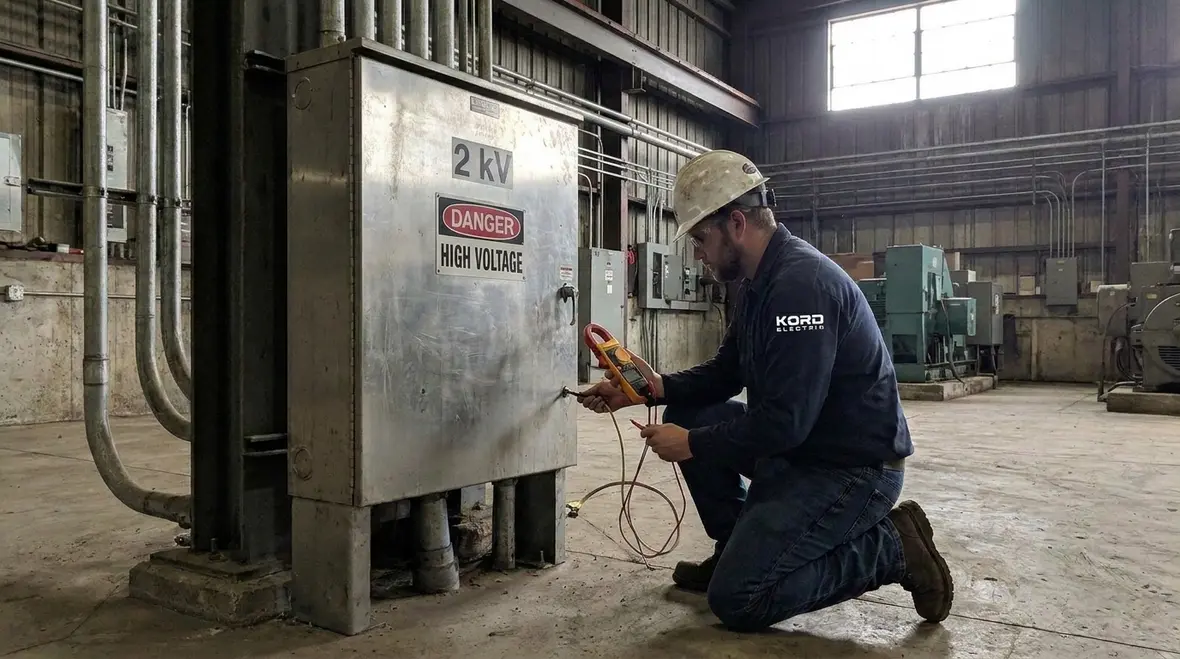
Section 270.148 lives inside Article 250 thinking, even though it appears under conductors and raceways planning. It aligns with the bigger goal of the NEC: when a fault happens, the system must provide a low impedance path so protective devices can operate. As a result, the equipment grounding conductor does its job from the equipment back to the service or source. Moreover, the NEC treats metal enclosures, boxes, and fittings as part of that path. If the path breaks, you may still get power. However, you might also lose the reliability of the safety function. And that is where the trouble begins, often quietly.
For facilities like data centers, light industrial buildings, campuses, and mixed major properties, our team sees two recurring realities. First, installers sometimes assume “the box is metal, so it must be grounded.” Second, at higher energy levels like NEC EGC boxes 2 kV applications, small attachment errors can create big issues. Therefore, we treat Section 270.148 as a field discipline, not a design afterthought. We also explain it the way our expert service staff explains it to operators and building managers: with clear cause and effect, not vague compliance.
What EGC continuity really means on a job site
In simple terms, EGC continuity means the equipment grounding conductor and the metal parts it connects stay electrically connected along the route. The NEC wants that connection to be durable and reliable, especially at points where installers attach boxes to systems. So, when equipment enclosures, pull boxes, and similar metal parts get connected to the grounding path, the attachment must support a stable low impedance connection.
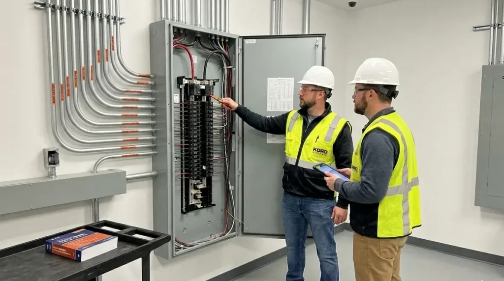
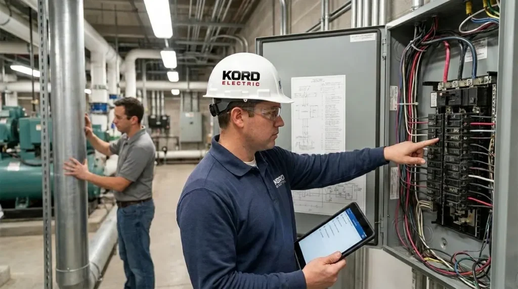
At Kord Electric, we verify continuity as part of quality control. Additionally, we look at how the box attaches to raceways or cable systems, because a loose or poorly secured box can act like an interruption in the grounding path. Next, we confirm that the EGC terminates correctly at both ends. Then, we check bonding bushings, fittings, and grounding means as they show up in the field. If someone cut a corner, we want to find it early, before the circuit energizes. That is how we keep commercial and industrial facilities moving, without turning maintenance into detective work.
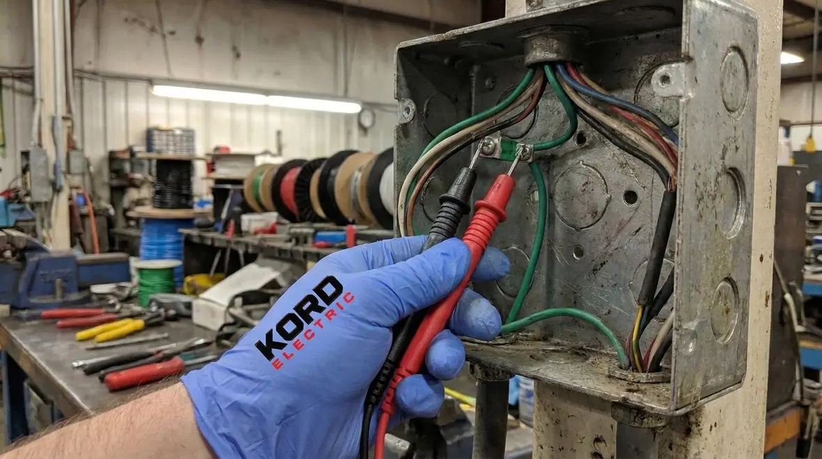
Box attachment at 2 kV: what the rule expects in practice
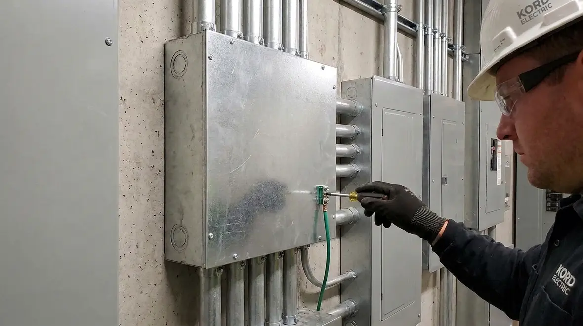
When we discuss NEC EGC boxes 2 kV requirements, we focus on the attachment points that carry both mechanical load and electrical bonding responsibility. Section 270.148 addresses how boxes must be attached so they support dependable grounding continuity. In addition, it recognizes that mechanical attachment and electrical bonding often travel together. If a box does not hold firmly, the bonding connection can loosen over time due to vibration, thermal cycling, and installation stress. Therefore, the code expects proper mounting and secure engagement of components.
Our technicians typically spot issues in three places. First, they check the physical attachment between the box and supporting construction or raceway system. Second, they inspect whether bonding methods create a full metal path without gaps. Third, they ensure any required bonding means remain intact during device installation. We do not treat this as a one time task. We treat it like a process that continues from rough-in to final trim-out, because reality rarely stops at the first inspection. And yes, sometimes a “small adjustment” becomes a “big rework.” We have seen that plot line. We usually just rewrite it before it starts.
Common field mistakes we prevent for major buildings
Commercial and industrial electrical work carries pressure. Schedules tighten. Crews rotate. Materials arrive late and subsystems overlap. So, even competent teams can miss bonding details when the job moves fast. That is why our expert service staff emphasizes practical checks during installation.
1) Assuming metal equals bonding
Metal parts can look bonded but still fail electrical continuity if attachment is loose or contact surfaces do not stay connected. Proper bonding methods matter.
2) Using the right parts, wrong locations
A bonding lug or fitting installed at the wrong point can leave the grounding path incomplete. We make sure the grounding path matches the intended electrical route.
3) Overlooking installation damage
During pulling, drilling, or device mounting, crews can scratch surfaces, bend conductors, or disturb box mounting. We check after the dust settles, not before.
4) Skipping continuity checks
If you do not test, you do not know. We use verification steps during commissioning so the building owner gets dependable results, not hopeful guesses.
In addition, we coordinate our steps with existing facility standards for major property buildings. That matters because older structures sometimes include upgrades layered over original work. When we meet that reality, we align new bonding and attachment methods with safe, code based practices.
How we verify compliance without slowing down your facility
We know that in a commercial or industrial building, safety work must still respect downtime limits. Therefore, our approach focuses on both compliance and job flow. First, our electricians review the system layout and the raceway or cable routing plan. Next, they confirm what the NEC requires for grounding and bonding at connection points. Then, during installation, we check box attachment and termination details before circuits get energized.
As we test, we also document what we find. This matters when ownership changes, when maintenance teams inherit the system, or when future modifications happen. Moreover, a clean record helps with inspections and helps your team maintain the system over time. If you want a calm, predictable process, we build for that. Not because we enjoy paperwork, though we do enjoy it slightly more than the typical “mystery breaker” calls. Those calls always seem to happen right before a holiday shutdown.
NEC context across related code themes
The NEC does not treat grounding as a standalone topic. It connects grounding, conductors, enclosures, and device rules into one safety goal. That is why our team also supports broader NEC understanding for building operators and facilities staff. We reference guidance from resources we trust, including NEC explainer content hosted by Kord Fire and Kord Electric, so our customers get a consistent picture of how the code works together across system design. Additionally, we keep an eye on how commercial fire and electrical coordination shows up in real life, because facilities operate as systems, not isolated parts.
We also maintain a practical lens. We may not talk about every section in every job, but we make sure the sections that affect safety and inspection success receive attention. For major property buildings, that includes how EGC paths stay intact at the points that see motion, stress, and changes during maintenance. In that context, Section 270.148 stands out because it directly impacts how boxes remain bonded and mechanically supported where grounding depends on them.
For teams who want a broader explainer of how NFPA 70 fits together before they tackle specific topics like EGC continuity, we often recommend pairing this guidance with our NEC focused companion articles. Resources such as the National Electrical Code explainers and grounding deep dives on the Kord Electric blog help connect Section 270.148 to related rules without turning your reading list into a self study marathon.
Dual column best practices for EGC continuity and box attachment
What we do during installation
- Confirm correct box mounting and secure attachment
- Verify bonding means and termination points align with the grounding path
- Inspect contact surfaces and eliminate loose connections
- Check after device and cover installation for any disturbed bonds
We keep this step tight, because small errors scale up fast in the field.
How we verify before energizing
- Test EGC continuity along the intended route
- Confirm protective device operation readiness
- Document results for facility records
- Coordinate with your maintenance team for clear handoff
We do it before power, not after an issue makes itself famous.
FAQ: NFPA 70 Section 270.148 and EGC bonding
How this ties into broader NEC planning and services
EGC continuity and box attachment at the 2 kV level do not live in isolation. They connect directly to how you size conductors, route raceways, and coordinate protection across entire systems. That is why many facility teams pair section specific work like NFPA 70 Section 270.148 with broader planning resources. Articles on topics such as NEC specific purpose load calculations, grounding for nonelectrical equipment, and farm or specialty load totals give decision makers a wider view of how the National Electrical Code holds everything together across building types and use cases.
When Kord Electric designs or upgrades a system, we also look at how the NEC grounding and bonding rules interact with fire and life safety expectations. In many projects, our work runs alongside Kord Fire’s protection services, so electrical behavior, emergency power, and suppression systems pull in the same direction instead of fighting each other. That alignment helps major property buildings clear inspections more predictably and reduces the odds that a late code conflict derails occupancy dates.
If your portfolio spans multiple facilities or high demand occupancies, our broader Los Angeles County electrical services can tie EGC continuity support into larger strategies for preventive maintenance, critical system readiness, and future upgrades. The same discipline we bring to NEC EGC boxes 2 kV work scales into panel replacements, data center infrastructure, entertainment venue power, and more.
Call Kord Electric for EGC continuity support
If your facility needs electrical work that stands up to code, inspections, and real-world operation, call Kord Electric. Our technicians and expert service staff explain the requirements in plain language, then we verify installation details that protect grounding continuity and safe box attachment. Whether you are planning a new project or correcting field issues, we help commercial and industrial teams move forward with confidence. Book a consult today and let us handle the grounding details while your facility stays in control.
From NEC EGC boxes 2 kV installations to wider electrical upgrades, we approach every project with the same mindset: build a grounding and bonding path that behaves the right way on your busiest day, not just on paper. If you are ready to line up Section 270.148 compliance with the rest of your NEC strategy, our team is ready to help.