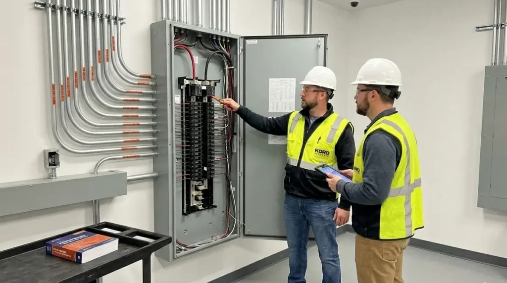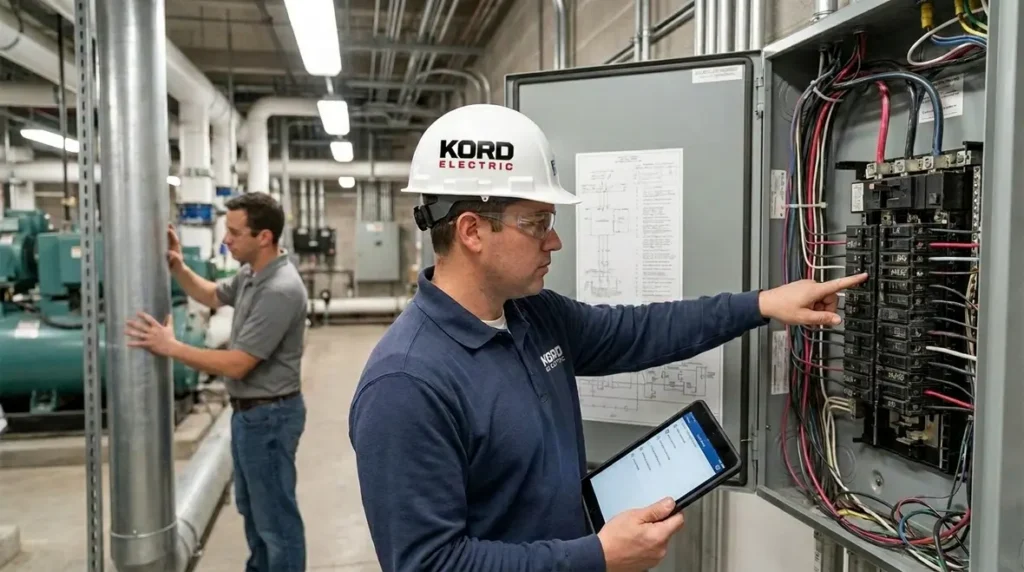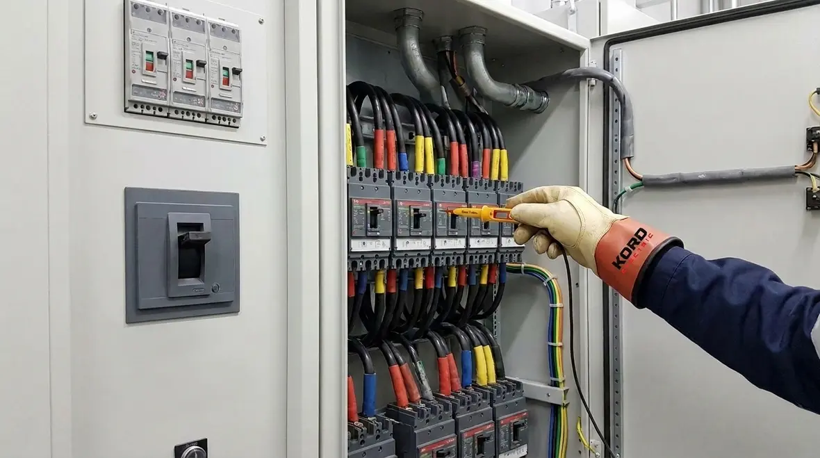
NFPA 70 Section 240.4 Conductor Overcurrent Protection
NFPA 70 Section 240.4 sits at the heart of conductor overcurrent protection, and our team at Kord Electric uses the same sizing math every day to keep commercial and industrial electrical systems safe and reliable. In plain terms, this rule helps decide how to protect conductors when the load changes, when insulation ages, and when equipment runs harder than anyone promised. So, if you are planning an upgrade, auditing existing feeders, or designing a new system for a major property, we translate the NEC conductor overcurrent protection steps into a clear method your maintenance team can actually follow. And yes, we also explain it with just enough humor to keep the meeting from turning into a silent vigil. Others may rush. We slow down, we check the numbers, and our expert service staff shows you why.
Why Section 240.4 matters for conductor protection
Third person readers who work around large facilities already know this: overcurrent events rarely start with a big dramatic bang. Instead, they often build quietly, then fail at the worst time. That is why NFPA 70 Section 240.4 focuses on how to size and protect conductors so protection matches the conductor’s ability to carry current safely.
To be clear, the NEC conductor overcurrent protection process is not guessing. It uses conductor ampacity, device ratings, and rules that limit how far equipment can push current. Next, it links to the practical reality that commercial buildings and industrial sites demand consistent safety margins, not last minute “good enough” decisions.
Our technicians and expert service staff do this work with care. Moreover, when we explain the conductor overcurrent protection sizing math on site, we tie each step back to the installed wire, the termination method, and the expected load behavior. People often think electricity stays put like paperwork. It does not. So, we make sure the protection follows the electrical facts, not the hope.
NEC conductor overcurrent protection sizing math, step by step
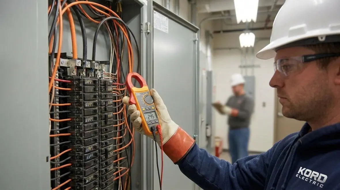
In the field, NEC conductor overcurrent protection is the difference between a breaker that trips at the right time and one that trips when the system least needs disruption. Therefore, the sizing math matters, and it is repeatable when someone follows the same sequence.
Here is the practical method many experienced electricians use for commercial and industrial systems.
- Step 1: Determine the conductor ampacity. The conductor ampacity comes from NEC tables and it accounts for insulation type and temperature rating. Then, adjustments may apply when there are more than three conductors in a raceway, or when ambient temperature conditions differ from the base assumptions.
- Step 2: Apply adjustment and correction rules. If the installation conditions reduce usable current, the ampacity changes. Consequently, protection must match the corrected value, not the original table number.
- Step 3: Check the overcurrent device size. The overcurrent protective device rating or setting must coordinate with the conductor ampacity and the NEC limits for conductor protection.
- Step 4: Confirm insulation and termination suitability. Overcurrent protection does not fix a bad termination. Therefore, the system must also meet connection and temperature rise expectations.
When our expert service staff walks a facility manager through this approach, we slow down enough to reduce mistakes. After all, a common “human error” is using an uncorrected ampacity number. It is like reading a speed limit sign upside down, then arguing with the ticket. The math does not care about the argument.
Matching ampacity and device ratings in real installations
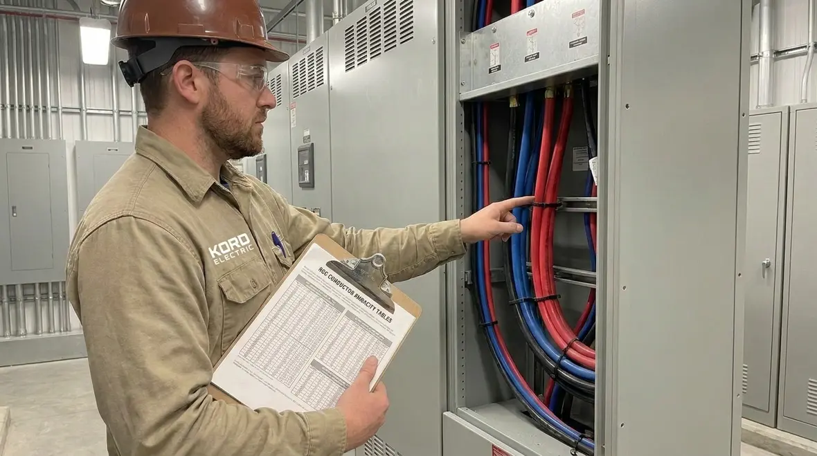
Commercial and industrial environments add complexity that residential work often avoids. There can be dense wiring in trays, higher ambient temperatures near motors, and multi-circuit raceways sharing space. Thus, the NEC conductor overcurrent protection math must reflect what is actually built, not what fits on a neat one line drawing.
Consider three real-world factors that influence how protection behaves.
- Conductor count in raceways or cables. When conductors share a conduit or cable assembly, heat builds up. Then the conductor’s usable ampacity can drop. If the design ignores this, the breaker may protect too late.
- Ambient temperature in equipment rooms. A boiler room does not share the climate of a clean office hallway. So, the correction factors matter when the installation runs hot.
- Continuous loads and load profiles. Many facilities run loads for long periods. Therefore, designers must treat continuous load behavior correctly, and they must verify the protection device will operate as intended.
Our technicians handle this by tracing the conductors from panel schedules to the physical routing. In addition, we confirm that the termination method and equipment ratings align with the design assumptions. Otherwise, the system may meet code on paper and still fail in practice.
How common exceptions show up at job sites
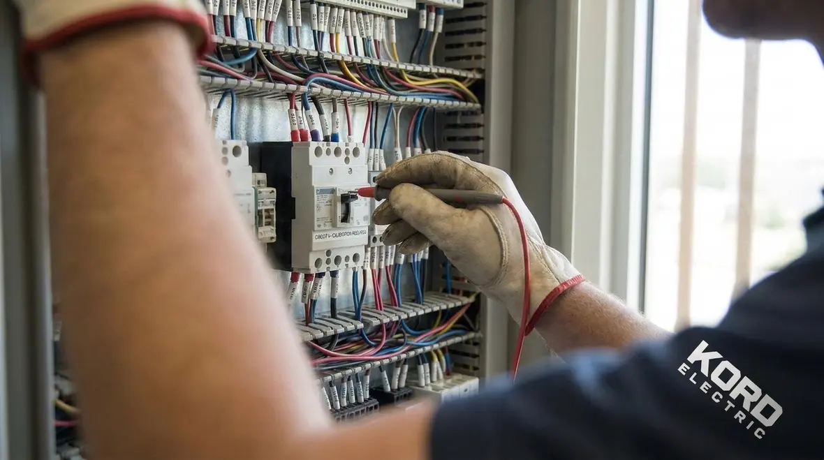
People love exceptions. They show up in code, they show up in emails, and sometimes they show up when nobody wants to redo a design. Yet, NEC rules allow only specific exceptions and conditions. So, our expert service staff treats exceptions like a controlled ingredient, not a free pass.
For conductor overcurrent protection, common trouble spots include:
- Using the wrong base ampacity. Adjustments for temperature or conductor grouping often get missed. Then the breaker ends up oversized relative to the corrected conductor ampacity.
- Confusing device rating with trip setting. Many modern breakers have settings that must coordinate with the load. If the design uses only the nameplate rating, it can drift away from the actual protection behavior.
- Skipping coordination review. Even when a breaker trips, it must trip at the right level to protect the conductor and reduce equipment damage. Coordination is not optional on critical systems.
Sometimes, a facility calls us after repeated nuisance trips. At that moment, they want a quick fix. However, our approach starts with the conductor protection math. Then we compare it against the existing conductor ratings and device settings. If the numbers do not align, we correct the design instead of applying a Band Aid. Electricity does not respect Band Aids. It respects physics, and it invoices you for mistakes.
Coordination in buildings with motors, feeders, and panels

Large commercial and industrial facilities rarely run on simple resistive loads. They run pumps, air handling equipment, conveyors, compressors, and whole networks of motor-driven systems. Consequently, conductor overcurrent protection must coordinate across panels, feeders, and branch circuits.
In practice, a motor circuit can include long conductor runs and starting current that spikes higher than steady state current. Therefore, protection must limit damage while still allowing the motor to start without constant tripping. At the same time, feeder protection must protect both the conductors and upstream equipment.
Our technicians often use a coordination mindset when reviewing designs and retrofit projects. First, they check conductor sizing for steady state and for installation conditions. Next, they verify breaker or fuse characteristics align with starting demands. Then, they evaluate downstream devices and upstream devices as a system, not as unrelated parts.
For customers who want deeper context on how the NEC frames the electrical code for major projects, Kord Electric also publishes guidance and explanations that support design teams and facility stakeholders. Kord Electric’s blog explains the NEC framework for 2026 and beyond, including resources such as Understanding NFPA 70: The National Electrical Code Explained for 2026, while Kord Fire and fire-focused resources reinforce how code thinking supports life safety in and around electrical systems. You can find supporting references at kordelectric.com and kordfire.com, along with additional background at kordfire.com.au and firepumps.org.
Documentation and compliance that holds up during audits
After the wiring is in, the real question becomes: can the facility show its work? Audits and safety reviews often request proof that conductor overcurrent protection sizing matched NEC requirements. So, Kord Electric supports documentation that stays consistent from design through install.
To keep the story clean, our expert service staff helps teams collect the following:
- Conductor type, size, insulation rating, and route
- Corrected ampacity calculations for ambient temperature and conductor grouping
- Overcurrent device ratings or settings and how they coordinate with the conductors
- Motor and load notes, including starting behavior where applicable
This is not “paperwork for paperwork’s sake.” It is how teams reduce downtime during inspections and how they defend the design logic under pressure. Moreover, it prevents the common cycle where someone changes a load later and nobody updates the protection math. We help you avoid that spiral before it starts.
FAQ about conductor overcurrent protection and Section 240.4
Quick FAQ for featured snippets
- Does Section 240.4 apply to branch circuits only?
It applies to conductor overcurrent protection where the NEC rules specify sizing of protective devices for conductors. - What causes nuisance trips?
Often it comes from incorrect ampacity calculations, wrong device settings, or load changes that were never rechecked. - Who should perform conductor protection reviews?
Facilities should use experienced technicians who understand NEC requirements and can verify wiring conditions on site.
Conclusion and next step with Kord Electric
When conductor overcurrent protection follows Section 240.4 with correct ampacity math, your system stays safer and your operations run calmer. Kord Electric serves commercial and industrial facilities and major property buildings, and we bring our technicians and expert service staff to the job with a method you can trust. If your project needs a protection review, a retrofit check, or an audit-ready documentation package, we are ready to help. Reach out to Kord Electric today, and let us tighten up the numbers before the next inspection tightens them for us.
If you are planning upgrades, renovations, or larger code-driven changes, you can also connect this conductor protection work with broader Los Angeles County electrical services support. Our team coordinates NEC conductor overcurrent protection, documentation, and inspection readiness so your next project moves forward with fewer surprises and clearer protection across feeders, branch circuits, and critical loads.