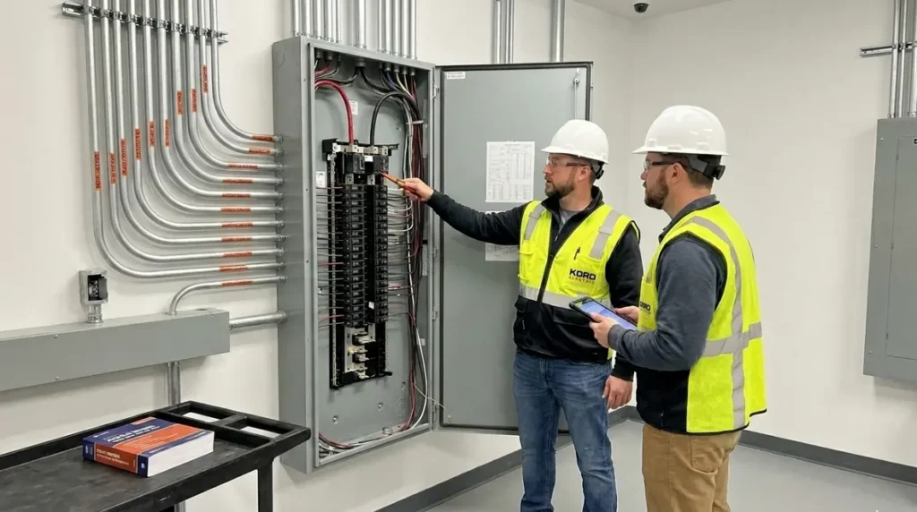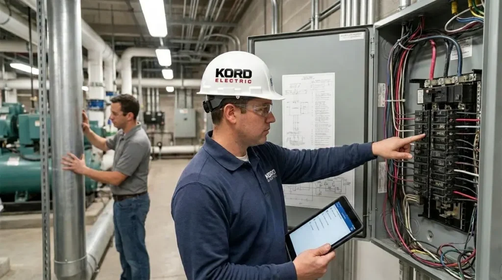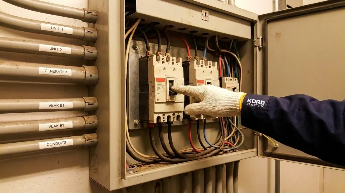
NFPA 70 Section 240.9 and NEC Thermal Overcurrent Devices
NFPA 70 Section 240.9 and why our NEC thermal overcurrent devices matter
At Kord Electric, we stand by a simple idea: if a system can fail, it will eventually try. That is why, in the first steps of design and service, we pay close attention to NFPA 70 Section 240.9. In plain terms, this rule focuses on thermal devices for overcurrent protection and how they should work when heat rises and conditions change.
To support our commercial and industrial customers and major property buildings, our team uses NEC thermal overcurrent devices and matching protection strategies so the right equipment trips at the right time. As our technicians explain during site visits, rules like 240.9 are not paperwork for paperwork’s sake. They help prevent fires, limit damage, and keep operations running. And yes, we also tell people that electricity does not care about your weekend plans.
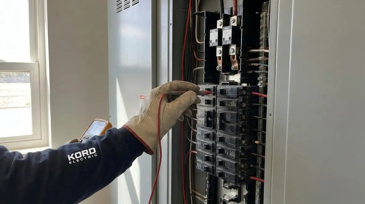
How Section 240.9 fits into the bigger protection picture
Others often think overcurrent protection starts and ends with a breaker. However, we treat protection as a layered system where heat, wiring limits, and device behavior all connect. Meanwhile, NFPA 70 provides those connections through sections that guide how devices respond to overloads and short circuits.
Section 240.9 focuses on thermal action. That matters because some hazards do not look dramatic at first. Instead, they build. A loose connection, a failing motor component, or a long-term overload can create heat long before anything “pops.” Therefore, thermal overcurrent protection helps catch problems early, while crews still have time to plan repairs.
During reviews, our expert service staff maps the load profile and checks what “normal” looks like in real conditions. Then we align the response of thermal devices with the electrical design. That approach helps avoid two common failures: protection that triggers too easily and protection that waits too long.
We also connect the logic of Section 240.9 to other NEC decisions our team makes across a facility. For example, when we review NEC available fault current marking under NFPA 70 110.24 or service overcurrent protection under Section 230.90, we keep the same principle in view: match device behavior to real system conditions, not just a drawing set that looked good on day one.
That same mindset appears in other Kord Electric code-focused resources, such as our article on NEC available fault current marking under NFPA 70 110.24 and deeper NEC topics like service overcurrent protection in 230.90 and grounded conductor disconnection in 230.75. Each of those decisions affects how overcurrent protection behaves, and together they shape the risk picture for commercial and industrial facilities.
What thermal devices do, in real building conditions
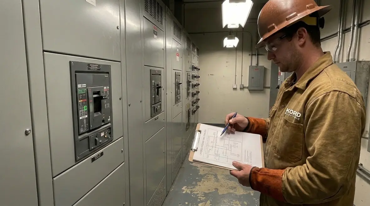
Thermal devices respond to temperature rise, not just current spikes. As heat grows, the device changes state, which then limits damage by interrupting the circuit or signaling the need for corrective action.
In the field, we see heat come from three places. First, overloads raise conductor temperature over time. Second, poor connections increase resistance and create localized heat. Third, environmental factors like heat buildup inside enclosures can make everything run hotter than expected.
Now, here is where it gets practical. When we install or service NEC thermal overcurrent devices, we do not treat them like a generic part number. We verify ratings and coordination. Then we consider how the device’s thermal response interacts with the load type, such as motors, transformers, and feeders in larger commercial and industrial spaces.
Our technicians also explain a key point: thermal response time is not a guess. It follows the device design. So if the building runs in a way that stresses the system, the device should behave in a way the code expects, not in a way that surprises the maintenance team.
We align these decisions with the broader National Electrical Code structure, including how NFPA 70 organizes requirements for service equipment, feeders, branch circuits, and labeling. That is why we reference resources like our in-depth NEC explanations for 2026 planning, so facility teams can see how thermal response ties back to conductor sizing, overcurrent ratings, and the markings that appear on real equipment.
Why “just a little extra heat” is still a warning sign
In practice, we treat “warm to the touch” components as a story, not a mystery. A breaker that runs hotter than expected, a lug that discolors over time, or a cable that feels warmer on one end than the other all point to conditions that NEC thermal overcurrent devices are meant to control. When teams ignore these early signals, they give small problems time to become expensive failures.
Coordination and selectivity: fewer unwanted outages, more controlled protection
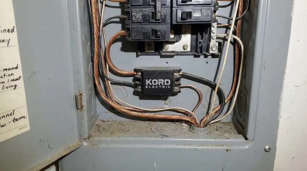
One of our most requested outcomes from facility managers is simple: less downtime. However, thermal protection and coordination decide whether the system interrupts only the faulty section or shuts down more than it has to.
When thermal protection works well, it isolates the fault and limits disruption. When it works poorly, crews end up resetting equipment like they are playing whack-a-mole. Meanwhile the real problem stays, quietly heating up somewhere else.
That is why we coordinate devices based on actual loads and protective settings, then we confirm that upstream and downstream components respond in the intended order. In large facilities, we consider feeder and branch behavior so the weakest link does not get blamed for the wrong job.
Our expert service staff uses site knowledge and code guidance to help ensure selectivity. This is especially important for major property buildings where shutdowns affect tenants, security systems, elevators, and life safety loads.
How NEC thermal overcurrent devices support real coordination plans
In a well-coordinated system, thermal elements are chosen with time–current curves that align with upstream devices. When a branch circuit overloads, the branch device should respond before the feeder device. When we design or review systems for customers, we compare these curves against real load behavior, including motor inrush, transformer energization, and intermittent process loads.
These coordination checks sit alongside other NEC-driven decisions, like available fault current marking, grouping of service disconnects, and clear branch circuit identification. Together, they turn a collection of devices into a coherent protection plan that behaves predictably during both minor overloads and major faults.
Common failure sources we look for before they become smoke alarms
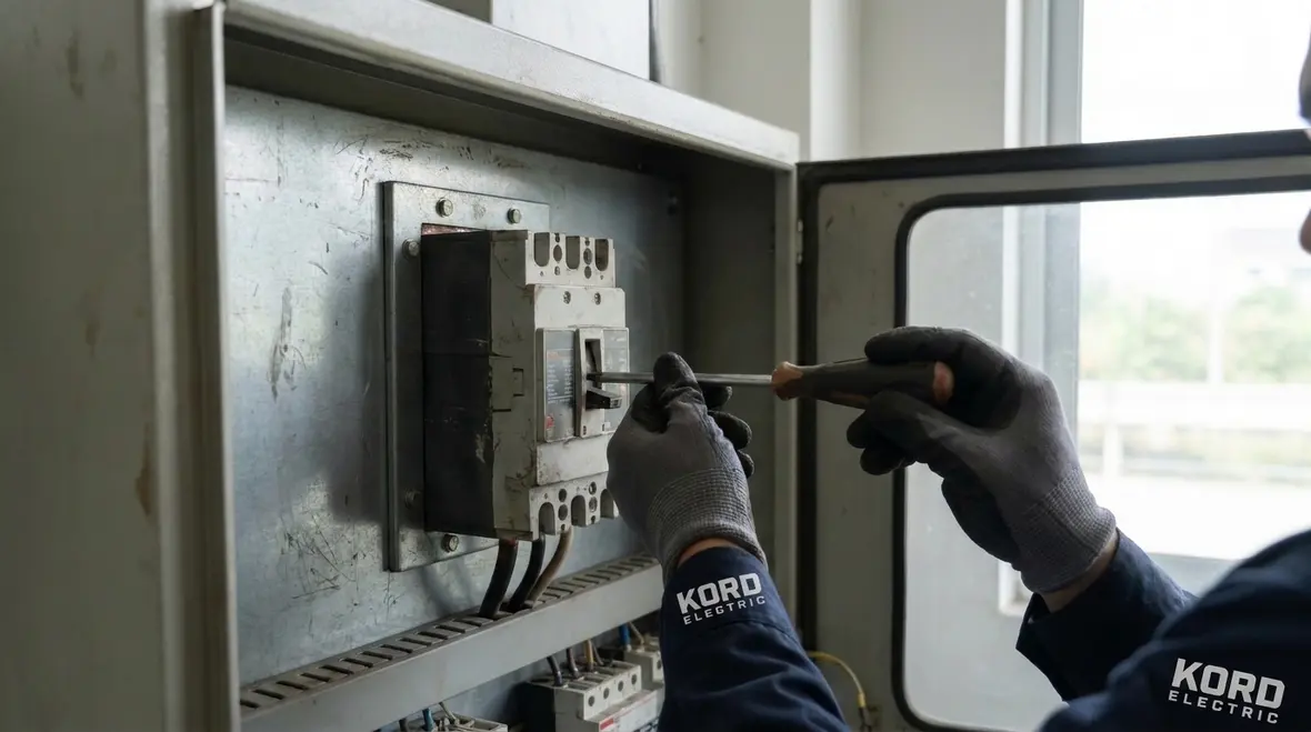
Thermal overcurrent protection can only do so much if the system setup invites heat buildup. Therefore, our service team focuses on root causes, not just symptoms. Even the best device cannot protect a wiring problem that keeps getting worse.
Here are the issues we check most often in commercial and industrial facilities.
Loose terminations that increase resistance and raise localized temperature
Incorrect device ratings that do not match the load characteristics
Damaged insulation that changes heat patterns inside conduit and wireways
Overloaded circuits due to changes in operations after the initial design
Cooling limits such as blocked ventilation in enclosures and closets
Then we add one more step that many teams skip. We review how the facility actually runs. Schedules shift. Equipment gets replaced. A “temporary” load becomes permanent, and that is how heat sneaks in like a prank that never ends. We treat these changes as part of the safety plan.
From checklists to continuous electrical reliability
Instead of treating inspections as a one-time event, we use them to build a living picture of the facility. That picture draws on the same NEC mindset we share in our educational resources: safe systems require clear identification, documented decisions, and periodic verification. With that approach, thermal devices are not seen as “the fix” but as one layer in a broader risk reduction strategy.
NEC compliance beyond the checklist: documentation, testing, and service plans
Code compliance is not only about choosing the right devices. It also includes documenting the decisions, confirming installation quality, and maintaining protection performance over time. This matters because devices age, environments change, and facilities evolve.
We work with commercial and industrial customers to build service plans that fit how the building operates. After all, a high rise and a warehouse behave differently, even if the wiring diagram looks similar on paper. We also follow a process that includes inspection and validation so the system stays reliable.
During service conversations, we often reference the broader NEC framework described in resources we support at our sites, including Kord Electric and Kord Fire and their NEC education pages. We also keep an eye on how fire protection guidance ties into electrical safety priorities for major properties.
For example, our teams regularly connect this topic with articles like “NFPA 70 Section 130.2 NEC EMS Listing Requirements Code,” “NFPA 70 Section 200.10 Terminal Identification Requirements,” and “NEC Lockable Disconnect Lockout Requirements for Teams.” Each article highlights a different piece of the NEC puzzle, but the underlying theme is the same: organized, documented electrical work prevents confusion when it matters most.
And in case anyone needs the reality check, the code does not reward “we will fix it later.” Later is usually when the problem costs more and interrupts operations.
Service planning that respects NEC intent
When we build a service plan around NEC thermal overcurrent devices, we schedule testing, torque checks, infrared scans, and documentation updates together. That way, thermal devices are always evaluated in the same frame as conductors, terminations, and labeling. The result is a protection scheme that not only meets NFPA 70 requirements but also makes sense to the people who operate and maintain the building every day.
How others should interpret thermal protection guidance for facility planning
Many facility leaders want a decision that “feels right” and does not disrupt operations. However, thermal device selection and use should follow the code logic and the building’s actual load behavior. So we encourage others to treat thermal devices for overcurrent protection as a design requirement, not a last-minute add-on.
To plan well, we recommend that teams ask how protection supports:
Motor and control loads that change during start and run conditions
Feeder performance under sustained operations
Enclosure heat where ambient conditions can shift device behavior
Maintenance access so service checks happen before failure
Then our technicians walk through the “why,” not just the “what.” We explain the thermal concept in plain language, we point to how the device responds, and we connect it to the facility risk picture. This calm, deliberate approach keeps the conversation useful. It also keeps people from arguing with the laws of physics, which is a losing hobby.
Teams that want to connect these ideas to the full code landscape can explore our resource “Understanding NFPA 70: The National Electrical Code Explained for 2026,” which takes the high-level NEC structure and translates it into field-ready guidance for the coming code cycle. That article pairs well with this discussion of NFPA 70 Section 240.9 and other focused topics like branch circuit identification and outside disconnect identification.
Planning upgrades with NEC thermal overcurrent devices in mind
When you plan an equipment upgrade, a new process line, or an expansion, include thermal protection decisions in the early design meetings. Ask where NEC thermal overcurrent devices will live, how they will be coordinated, and how future technicians will understand their settings. That mindset keeps you aligned with NFPA 70 Section 240.9 and reduces surprises during inspections or commissioning.
FAQ: NFPA 70 240.9 and thermal overcurrent protection
Call Kord Electric for a safe, code-aligned protection plan
If you manage a commercial or industrial facility or a major property building, do not leave protection to chance. Kord Electric can review your system design, verify the fit of NEC thermal overcurrent devices in the context of thermal behavior and coordination, and help you build a service plan that reduces downtime and risk. Call us to schedule an on site assessment with our technicians and expert service staff. We will explain what we find, what we change, and why, in clear business language.
As part of that review, we can also connect NEC thermal overcurrent decisions to related topics such as available fault current marking, service overcurrent protection under Section 230.90, lockable disconnect requirements, and branch circuit identification. If your facility is located in the region we serve, including Los Angeles County electrical services for commercial and industrial properties, we can integrate those upgrades into a unified project plan rather than a set of disconnected fixes.
For facility teams who want to keep learning between visits, we recommend pairing this article with our NEC education content, including “Understanding NFPA 70: The National Electrical Code Explained for 2026” and topic-specific guides on NFPA 70 Section 230.72 grouping service disconnects, Section 225.37 outside disconnect identification, and Section 200.10 terminal identification. Together, those resources turn the code from an obstacle into a roadmap.