NFPA 70 Section 270.144 NEC Multiple Circuit EGC 2 kV
At Kord Electric, we work every day in commercial and industrial facilities, and we also support major property buildings where electrical systems have real consequences. That is why we take NEC multiple circuit EGC 2 kV seriously, especially when an installer or owner has multiple conductors and paths that can interact above 2 kV.
In this article, we explain NFPA 70 Section 270.144 and how it governs the rules for the equipment grounding conductor when you run multiple circuits. We also describe how our technicians and expert service staff help teams follow the code, document decisions, and avoid costly mistakes. And yes, we keep the tone calm, because nobody needs panic on a switchgear floor. Well, maybe just a little when the breaker label is upside down.
NFPA 70 Section 270.144: what it means for NEC multiple circuit EGC 2 kV
NFPA 70 Section 270.144 focuses on what happens when multiple power circuits above 2 kV share equipment grounding arrangements. In a small system with only one feeder, the grounding story feels straightforward: you size an equipment grounding conductor (EGC), route it with the circuit, and verify that fault current has a fast, low-impedance path back to the source so overcurrent devices can do their job. In larger systems, that story gets more complicated—especially once multiple circuits, shared raceways, and complex switchgear enter the picture.
The section is there to prevent an all-too-human shortcut: trying to “simplify” multiple circuit grounding by cutting corners on how the EGC is arranged, connected, or consolidated between circuits. It defines how equipment grounding conductors must be treated when several medium-voltage circuits operate in the same general system so that a fault in one circuit cannot quietly turn into a hazard somewhere else.
Put simply, Section 270.144 exists so that the path the fault current wants to take is the same path the designer intended—and not a surprise tour through structural steel, cable trays, and equipment enclosures that were never meant to be the star of the show. When done correctly, personnel protection, equipment protection, and coordination with protective devices all get better. When ignored, grounding becomes the weak link that only shows up under stress.
Where Section 270.144 fits in real installations
Third person eyes matter here because, on large job sites, the “code conversation” does not stay only in the office. First, engineers set design intent, then electrical contractors install, and finally the facility team operates and maintains. Section 270.144 sits in that path and tells everyone what happens when multiple power circuits above 2 kV share grounding arrangements.
To make it practical, we look at these systems as networks, not isolated lines. Additionally, when a project scales, designers often use bus ducts, transformer feeds, metal-clad switchgear, and long raceway runs that include several circuits. Therefore, grounding conductors must stay consistent with the code requirements for safety and fault clearing.
In other words, the rule is not there to slow down work. Instead, it helps keep energized parts from becoming energized cases. And if that sounds obvious, that is only because the rules were written by people who learned the hard way, often after equipment damage, downtime, or a near miss that everyone remembered for years afterward.
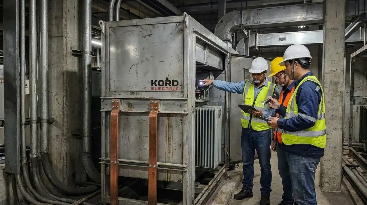
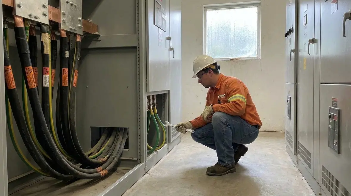
On the design table, Section 270.144 shows up as notes on one-line diagrams, grounding details, and specifications. In the field, it shows up as how equipment grounding conductors are run in cable trays, duct banks, and conduits—how they terminate at switchgear, transformers, motors, and disconnects, and how they remain continuous through pull boxes, splices, and transitions. When Kord Electric reviews a project, we trace that story from design to field conditions, looking for places where multiple circuits share hardware and where the EGC philosophy really matters.
That is also where coordination with other safety and reliability efforts comes in. When a property manager is dealing with fire safety, power quality, and emergency power at the same time, grounding strategy has to line up with more than just a single drawing set. That is why we pay close attention to how Section 270.144 interacts with other NEC requirements, NFPA expectations, and site-specific reliability goals.
EGC basics above 2 kV, explained without the mystery
Above 2 kV, grounding does more than provide a path. It supports fault current flow so protective devices clear fast enough to reduce shock risk, equipment damage, and fire hazards. Even when everything “seems fine” during normal operation, a fault turns the electrical system into a very different place. So the equipment grounding conductor must be sized, connected, and arranged correctly.
However, Section 270.144 focuses on a specific scenario: multiple circuits in the same general system above 2 kV. So while EGC concepts still apply, the rule adds limits and permissions about how you handle the EGC among those circuits. It is not enough to say “we have a ground somewhere in that duct bank.” The path, impedance, and continuity all have to match the code requirements and the fault studies that your protective device settings depend on.
Our technicians often explain this on site with a simple analogy. One circuit may be a single train track. When you add multiple tracks and switches, the right routing matters. If you route it wrong, the trains still move, but trouble arrives faster than anyone wants. A well-designed equipment grounding system above 2 kV behaves like a signal system that keeps those trains in line: predictable, coordinated, and prepared for what happens when something leaves the rails.
We also connect the basics back to the rest of your electrical strategy. If you are already thinking about surge protection, emergency power, or load balancing across feeders, then the grounding approach for your medium-voltage circuits is not a side issue. It is one of the foundations that keeps all those other investments working the way they should when the system is under stress.
How multiple circuits change the EGC rules
When multiple circuits above 2 kV exist, installers may be tempted to consolidate equipment grounding conductors to reduce labor or material cost. Yet the code does not treat consolidation as “free.” Instead, it requires that the EGC arrangement meet safety intent under fault conditions, including how fault current divides between paths and how overcurrent devices see and clear those events.
Section 270.144 addresses that by setting how the equipment grounding conductor can run and how it must connect across the grouped circuits. It also clarifies that grounding paths must maintain continuity and proper connection points, so fault current has a reliable return path. If one medium-voltage circuit faults to an equipment enclosure, the current has to find a low-impedance way back that does not depend on questionable bolted joints, unbonded trays, or “temporary” hardware that has been in place for ten years.
Therefore, the rule pushes teams to think about the grounding system as a coordinated assembly. In practice, Kord Electric helps commercial and industrial facility teams review one-line diagrams, conductor schedules, and equipment connection points before installation. Then we compare the plan to the requirements, so nobody has to guess during commissioning.
And just in case someone jokes about “code as a suggestion,” our experts respond with the calm confidence of someone who has replaced melted hardware after a fault. The joke ends quickly. The lesson lasts longer. Once you have seen a fault travel along an unintended path through shared metalwork, the appeal of a clean, code-aligned EGC arrangement becomes very obvious.
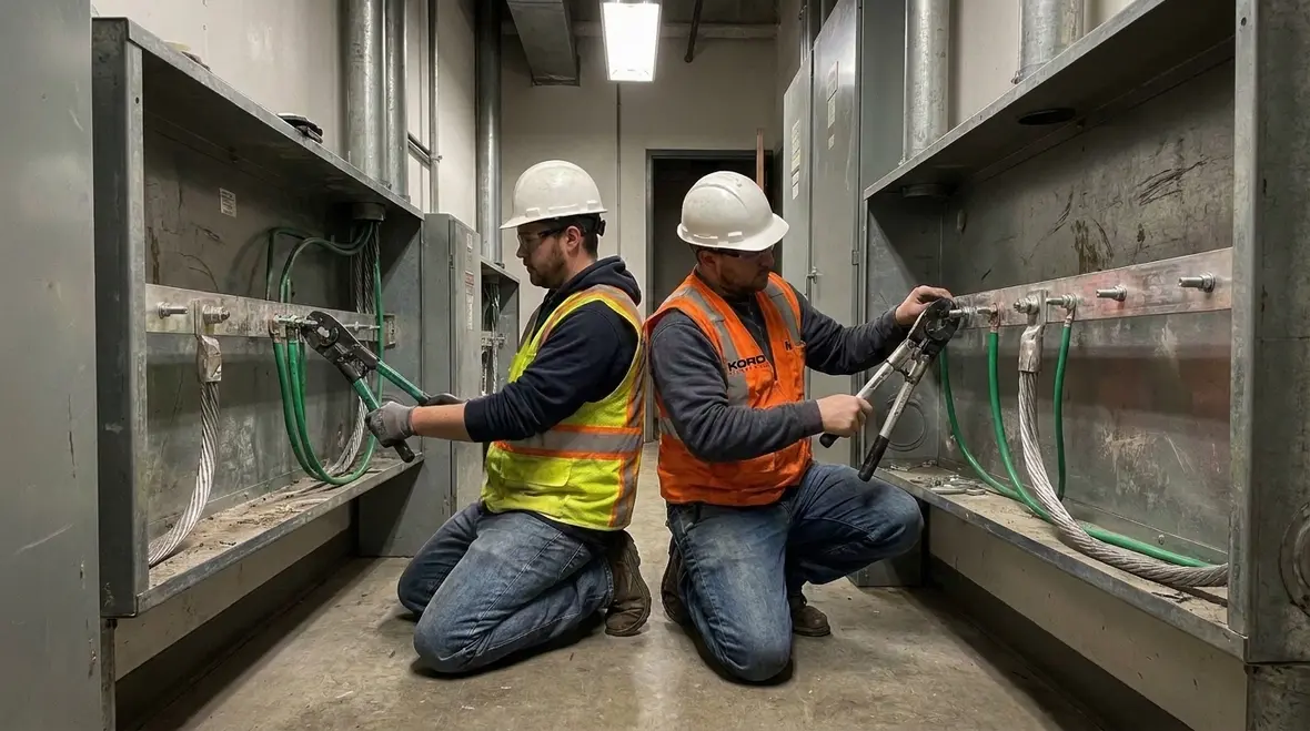
Common compliance mistakes in facilities and property buildings
Many failures we see during troubleshooting do not come from a single dramatic error. Instead, they come from small omissions that multiply across multiple circuits. The system may function for years without an obvious issue, until a fault lands in exactly the wrong spot and suddenly everyone discovers what the grounding plan really looks like.
Misunderstanding bonding and grounding intent: A team may bond for normal operation but miss the return path needs during a fault. The result is equipment that appears grounded but does not carry fault current where it needs to go.
Skipping required connection points: Some designs show a conductor run, yet omit a critical connection at a cabinet, raceway, or equipment frame. In multiple-circuit systems, that missing link can leave an entire section of gear depending on incidental contact instead of a deliberate bond.
Assuming consolidation always works: When multiple circuits above 2 kV share arrangements, the EGC rules must still meet the strict safety criteria. Bundling everything into a single grounding path without checking fault levels, impedance, and code language is a recipe for nuisance trips at best and dangerous touch voltages at worst.
Inconsistent documentation: Drawings may show one conductor arrangement while field installation follows another. Then maintenance teams lack clarity, and inspection teams flag the mismatch. In a medium-voltage environment, that confusion can delay repairs when time matters most.
Neglecting labeling and maintenance access: Even if the grounding path is correct, unclear identification can delay corrective action later. When everything in the gear room looks like the same green conductor with no labels, troubleshooting takes longer and temporary fixes become more tempting.
To reduce these risks, we rely on the kind of field work where our technicians explain the “why” behind each step. For example, we show how a grounded path supports breaker operation and how proper routing helps maintain continuity. After that, our expert service staff helps teams build a package that supports inspection readiness, complete with updated one-lines, marked-up drawings, and photos of critical terminations.
Commercial and industrial facilities cannot afford uncertainty. Major property buildings also need grounding systems that last through renovations, expansions, and equipment swaps. When a new tenant build-out or process upgrade happens three years from now, you want the EGC strategy you choose today to hold up without surprises.
Practical steps Kord Electric uses to verify EGC alignment
When Kord Electric supports a project, we do not treat code compliance as a final checkbox. Instead, we verify early, then verify again after installation, and we close the loop with clear documentation. That approach keeps quality high and reduces downtime risk.
Here is how we typically handle it, step by step.
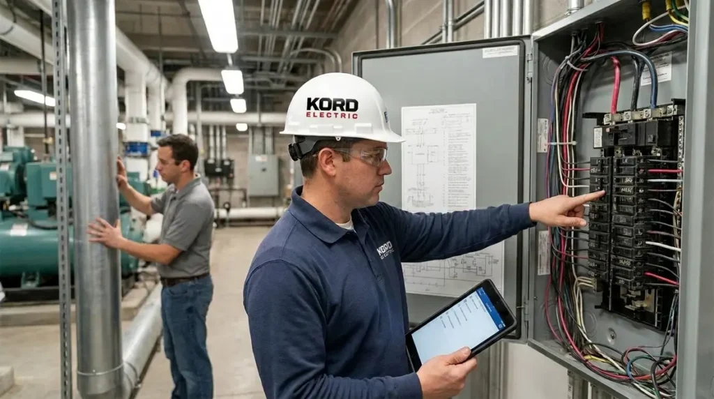
Review the design package: Our team checks the one-line diagram, raceway routes, equipment schedules, grounding details, and any notes tied to NEC multiple circuit EGC 2 kV decisions. We confirm that the narrative for multiple circuits and their shared paths makes sense before anyone pulls cable.
Confirm grouping logic for multiple circuits: We verify how circuits relate and ensure the EGC strategy matches the “multiple circuits above 2 kV” scenario, not just a copy-and-paste from a simpler low-voltage job. That includes looking at how feeders enter and leave gear, how they share metallic raceways, and how the grounding conductors are called out.
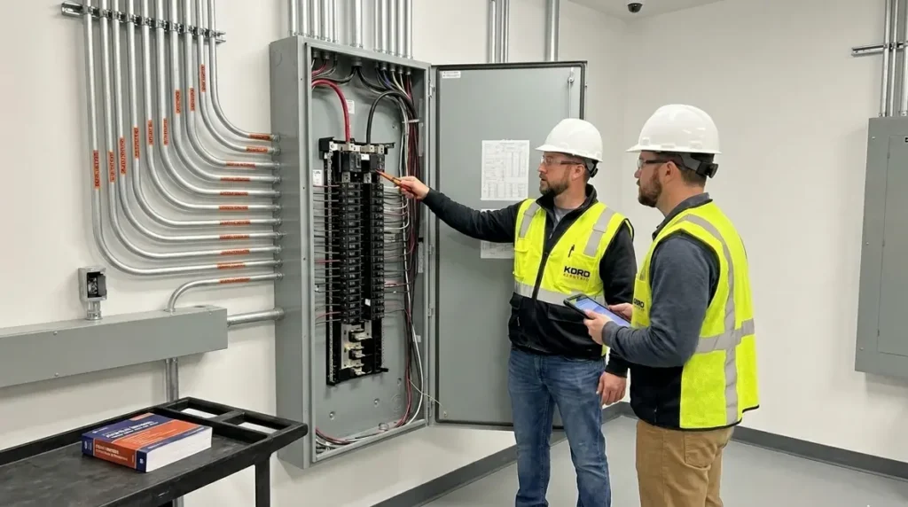
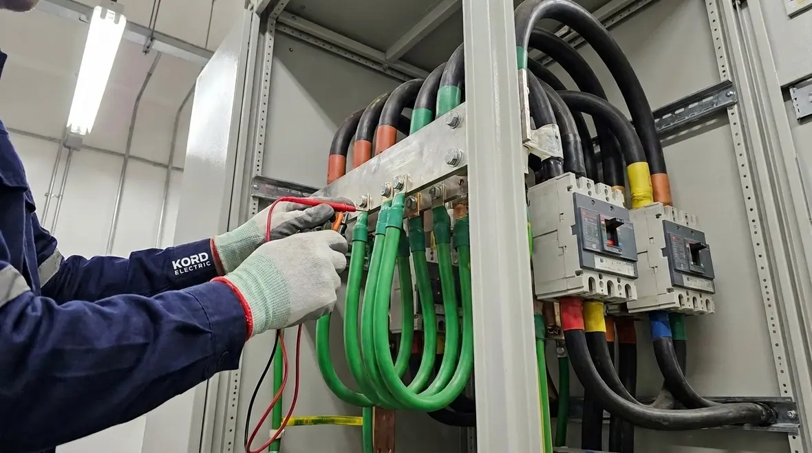
Inspect connections and continuity: We check frames, enclosures, bonding points, and transitions between raceways and equipment. Our technicians look for the quiet problems: paint under lugs, missing bonding jumpers, loose hardware, and terminations that do not match the detail drawings.
Verify conductor size and routing: We confirm the installed conductor meets the required sizing approach and that routing supports safe fault current return. That includes validating that EGCs remain effectively parallel to their associated phase conductors and that no improvised shortcuts were taken around structural obstacles.
Coordinate with commissioning: We support functional checks so field findings match the design intent before final acceptance. When protective relays, breakers, and fuses are tested, we make sure the grounding system they rely on was actually built as designed.
Provide clear closeout notes: We help facility teams understand what was installed and why, so future work stays safe and consistent. That includes marking where multiple circuits share grounding hardware, so maintenance and project teams know what they are touching years down the line.
Meanwhile, our communication style keeps things business casual but firm. We explain in plain language, then we show how it connects to fault protection. As our service staff often says, “If the grounding plan does not make sense to the person who will maintain it, it will eventually fail in a way that costs real money.”
How to keep grounding systems safe through upgrades and future loads
Commercial and industrial facilities rarely stay still. Loads expand, switchgear configurations evolve, and power systems get updated to support new processes. Therefore, the grounding system must remain coherent even after changes. If future projects add more circuits above 2 kV, your original Section 270.144 strategy has to stretch gracefully, not snap.
In a major property building, a renovation might add new circuits above 2 kV, or it might reroute feeders into existing gear. When that happens, facility teams need to treat grounding as a living system. They should validate whether any new circuits fit the “multiple circuits above 2 kV” rules and whether the EGC arrangement still matches the code intent. That may mean revisiting fault studies, rechecking EGC sizing, and confirming that new paths do not accidentally bypass the original grounding logic.
Additionally, Kord Electric encourages a simple discipline: when someone modifies the electrical system, someone else verifies the grounding path still supports safe fault clearing. Our technicians can explain the impact in meetings and on site, so stakeholders make informed decisions. That reduces the chance of “it worked before” becoming a dangerous slogan.
For broader NEC and safety context, Kord Electric also references trusted guidance from related code-focused resources and partner education efforts, including work from Kord Fire that explores NFPA codes and guidelines for life safety. Aligning electrical grounding, fire protection, and emergency power keeps your building ready not just for normal operation, but for the moments when everything gets tested at once.
If your team wants to dive deeper into how grounding connects to broader electrical reliability, articles like Kord Electric’s guides on data-driven electrical design, electrical load balancing, and power quality offer helpful context. They show how planning, modeling, and field verification keep all parts of the power system—including the medium-voltage EGC plan—pulling in the same direction.
Connecting NEC grounding strategy with real-world services
Understanding NFPA 70 Section 270.144 and NEC multiple circuit EGC 2 kV requirements is one thing; applying them across busy commercial and industrial facilities is another. That is where service coverage, coordination, and experience with similar projects really matter. Medium-voltage work touches everything from transformers and main switchgear to long feeder runs that support critical production lines or building infrastructure.
Because Kord Electric focuses on commercial and industrial facilities and major property buildings, our teams encounter these multi-circuit grounding questions on a regular basis. We see them in campus-style distributions with several feeders leaving a central plant, in high-rise properties with stacked gear rooms, and in specialized facilities that rely on medium-voltage equipment to keep operations running smoothly.
Across Los Angeles County, property managers and facility owners often pair their grounding and NEC compliance work with broader projects like surge protection improvements, emergency power design, or preventive maintenance. When those efforts are coordinated, you gain a clearer picture of how your EGC strategy interacts with fault protection, fire safety, and uptime goals instead of treating each topic as a separate conversation.
If your facility is planning major electrical upgrades, you can also look at how our Los Angeles County electrical services for commercial and industrial properties support inspections, testing, and installation under one coordinated plan. That way, your NEC grounding requirements, including Section 270.144, stay aligned with how crews actually build and maintain the system in the field.
FAQ
Conclusion and call to action
Kord Electric helps commercial and industrial facilities handle NFPA 70 Section 270.144 with clarity and confidence. We review the design, verify field installation, and document the grounding strategy so teams can operate and maintain with less risk and fewer surprises. If your project includes switchgear, transformers, or multiple circuits above 2 kV, our technicians can walk you through the EGC requirements and support compliance from plan to commissioning.
Whether you manage a high-rise property, a production facility, or a complex campus, a well-executed NEC multiple circuit EGC 2 kV strategy forms part of the backbone that keeps your electrical system safe under real fault conditions. Reach out to Kord Electric and get a grounding plan built to stand up under real conditions, not just pass a quick glance at inspection time.