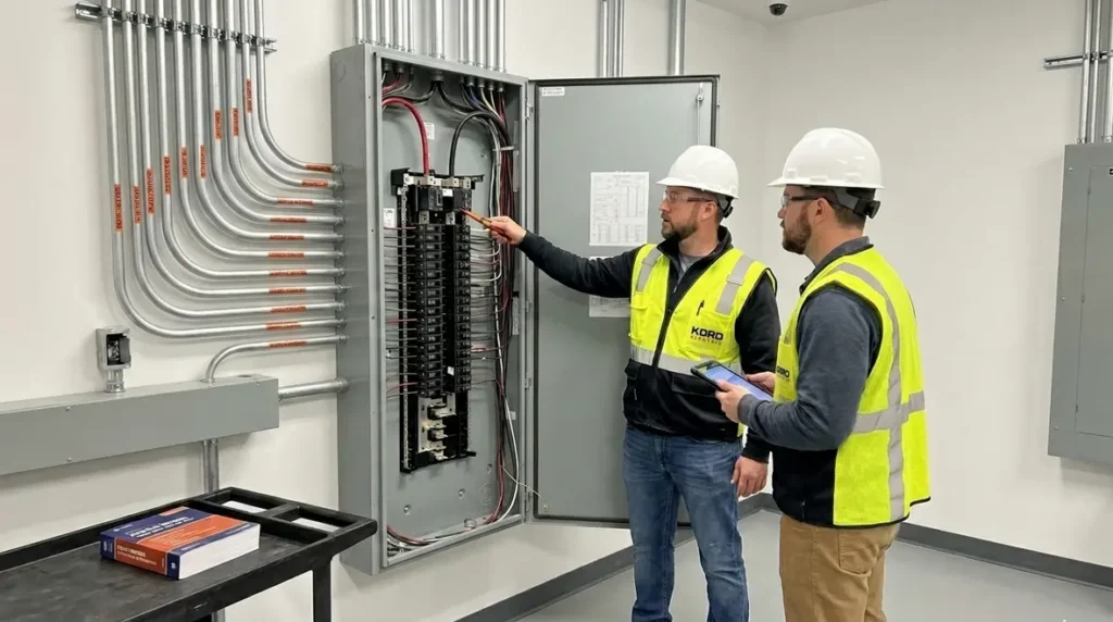
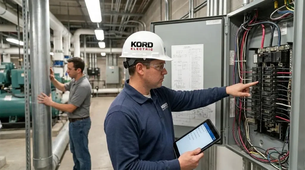
NFPA 70 Section 270.4 NEC Grounding Bonding 2 kV
NFPA 70 Section 270.4 sets the tone for how we handle NEC grounding bonding 2 kV when systems go beyond the 2,000 volt mark. In this article, we explain the big picture of Grounding and Bonding Over 2 kV and why it matters for commercial and industrial facilities and major property buildings. We do not treat it like a “checkbox code.” We treat it like a safety system that keeps people protected, limits damage during faults, and helps your power system perform when it matters most.
Now, let’s slow it down. Picture electricity like a loud neighbor with a strong opinion about physics. If the grounding and bonding plan is wrong, that neighbor does not just knock on the wall once. They keep at it, and eventually something breaks. The good news is that our technicians and expert service staff explain this clearly, so facility managers and electrical contractors can make correct decisions with confidence.
Why Section 270.4 matters for commercial power
Section 270.4 focuses on NEC grounding bonding 2 kV rules for systems above 2 kV. Above this threshold, the risk profile changes. Fault currents can be higher, touch and step voltages can become more dangerous, and small gaps in planning can turn into major failures during abnormal conditions. And because most commercial and industrial sites run critical loads, downtime costs real money, not just feelings.
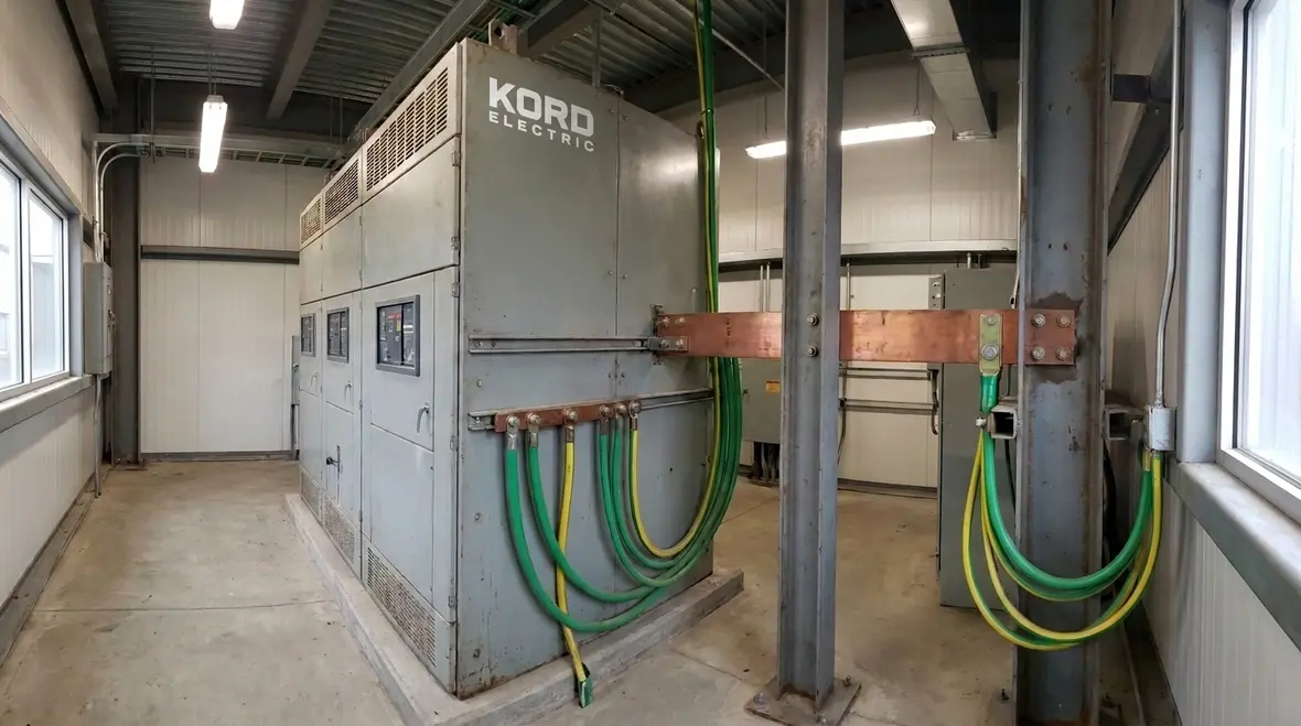
In practice, Section 270.4 connects grounding and bonding design to how equipment behaves during faults. It also ties into coordination between utility interfaces, switchgear, transformers, and the grounding electrode system. If those pieces do not talk to each other, your electrical system can act like a team with mixed instructions. Someone will get hurt, or you will pay for expensive repairs. Ideally, you pay for none of that.
Grounding and bonding: the roles people often mix up
We see this confusion often. Some people treat grounding like a single thing, but it is not. Grounding provides a reference point for the electrical system and helps clear faults. Bonding connects conductive parts so they share the same electrical potential. When we use both correctly, the system reduces dangerous voltage differences across metal parts that people might touch.
So, when we discuss NEC grounding bonding 2 kV in the context of NFPA 70 Section 270.4, we mean an engineered approach. We mean clear conductors, correct connections, and proper separation where required. We also mean that metallic parts stay at safe potentials during faults. That is why our technicians explain both the intent and the practical installation details, rather than handing over a vague summary and hoping for the best.
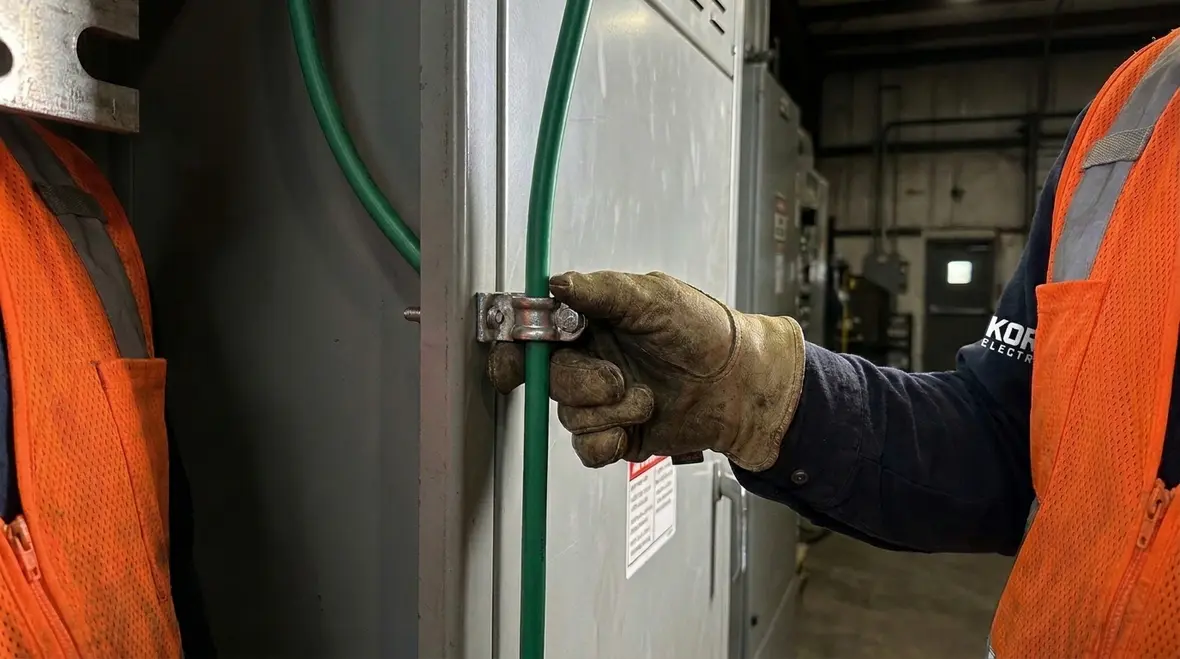
How the 2 kV threshold changes design decisions
Once systems pass 2,000 volts, the code expects more careful attention to how the grounding and bonding are applied. Facility owners and contractors must consider conductor sizing, connection methods, and how the grounding system ties together. Additionally, design must account for how fault currents can flow and how long they can persist before protective devices clear the fault.
At this level, we also consider the reality on the jobsite. Equipment layouts change. Conduits get routed. Ground conductors get longer. Connections get made under time pressure. That is exactly where good planning saves you. Our expert service staff commonly helps facilities by reviewing plans, verifying field conditions, and making sure the installed system matches the design intent.
And yes, it is possible to get it wrong even with good people on site. Electrical work punishes wishful thinking. If you want a pop culture comparison, it is like trying to build a stunt scene without checking the harness. You can guess. Or you can verify.
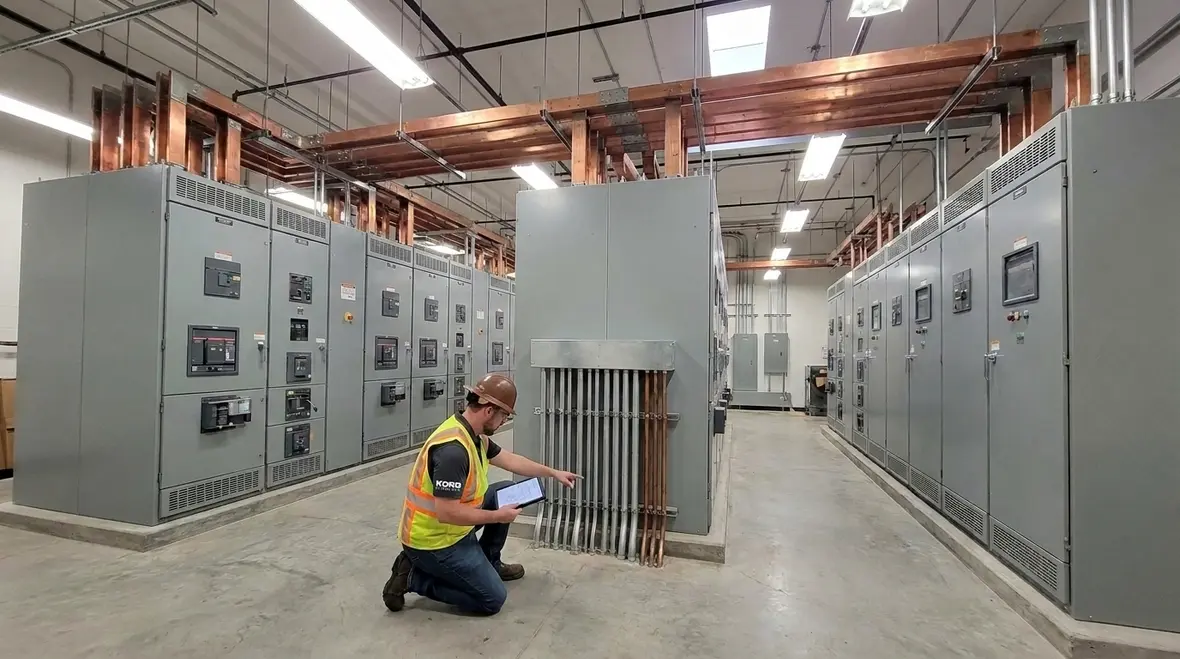
Bonding points and conductive parts in higher voltage systems
In higher voltage installations, bonding targets specific conductive parts so they do not develop harmful voltage differences. That includes metal enclosures, cable sheaths where applicable, frames, and other parts that can become energized due to faults. The goal remains steady: keep conductive objects at substantially the same potential under fault conditions.
What changes for NEC grounding bonding 2 kV is how carefully we must manage those connections. Designers and installers must ensure bonds are low impedance, robust, and properly located. Connections must also resist corrosion and mechanical stress over time. In commercial and industrial buildings, where maintenance cycles and environmental conditions vary, this is not optional. It is part of long term safety.
Also, bonding does not work alone. Grounding and bonding coordinate with overcurrent protection, fault detection, and equipment insulation. In other words, the grounding system supports the protective system, and the protective system limits how the grounding system must respond.
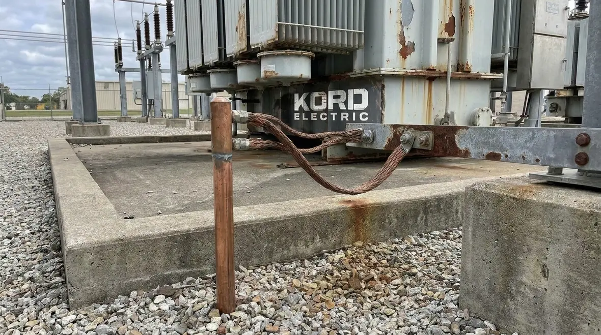
Fault behavior, touch voltage, and why clear plans prevent damage
Section 270.4 ties back to what people experience during faults. When a fault occurs, current can spread through conductive paths. The grounding system affects the distribution of voltage within the site. Bonding reduces differences between conductive surfaces.
As a result, the design helps limit touch voltage and step voltage around equipment. It also supports faster fault clearing by providing an effective electrical path for fault current. That means fewer failures, less equipment stress, and reduced risk to occupants, workers, and contractors.
We often explain it this way during consults with facility teams. If the grounding and bonding system is designed well, it behaves like a confident conductor. If it is not, the system becomes a chaotic playlist. You still hear music, but you also hear the sound of expensive lessons.
For major property buildings with multiple switchgear lineups, transformers, and feeders, we also help teams align the grounding plan across electrical rooms, equipment yards, and service entrance areas. The system must remain consistent from the utility interface through the facility distribution network.
Implementation steps for commercial and industrial facilities
Our approach at Kord Electric focuses on practical execution for commercial and industrial facilities and major property buildings. We do not just interpret text. We translate it into field-ready steps.
First, we confirm the system voltage level and the arrangement of service equipment, switchgear, and transformers. Then we review the grounding electrode system and how it connects to the higher voltage components. Next, we validate the bonding points and ensure they connect the right conductive parts using suitable methods.
After that, our technicians verify conductor routes, connection locations, and termination quality. We also check continuity and physical integrity. Finally, we coordinate with commissioning and maintenance plans so the grounding and bonding system remains effective over time.
Where facilities need a deeper conversation, our team draws from resources like the NEC discussions found on our related sites, including Kord Fire content about the NEC and code intent. You can explore more at kordfire.com/nfpa-70-all-about-the-national-electrical-code-nec and our Understanding NFPA 70: The National Electrical Code Explained for 2026 guide for broader code context. We also keep our focus on real building conditions, especially in sites where fire and life safety coordination matters. For fire pumps and related systems, teams often benefit from guidance aligned with industry groups such as firepumps.org.
Common mistakes that create long term risk
Even well meaning teams can miss details. Here are issues we see around NEC grounding bonding 2 kV installations and how we help prevent them.
- Missing or incorrect bonding connections: Equipment frames and enclosures may look bonded, but the actual path may be weak or incomplete.
- Improper conductor sizing or materials: Higher voltage systems can demand careful conductor choices for durability and performance.
- Loose terminations or poor connection quality: A connection that looks fine today may loosen later from vibration, thermal cycling, or maintenance activity.
- Electrode system mismatch: If the grounding electrode system does not align with the rest of the design, the system can fail to maintain safe potential during faults.
- Uncoordinated upgrades: When contractors add equipment without reviewing the existing grounding and bonding plan, they can create islands of conductive parts that do not share the right potential.
Our expert service staff addresses these risks through documentation review, field verification, and targeted corrections. We explain what we find in plain language, and we also explain why it matters so facility teams can plan future work with less guesswork.
FAQ
Conclusion: let Kord Electric help you get it right
If you run commercial and industrial facilities or major property buildings, NFPA 70 Section 270.4 is not background noise. It shapes how your higher voltage systems behave during faults, and it protects people, equipment, and budgets. Kord Electric brings expert service staff and experienced technicians who explain the “why” and verify the “how” in the field. If you want help aligning higher voltage design, testing, and long term maintenance, you can also review how our Los Angeles County electrical services support complex commercial and industrial power systems across the region.
Contact us today to review your grounding and bonding plan, verify that your NEC grounding bonding 2 kV strategy matches Section 270.4 expectations, and reduce long term electrical risk with confidence.