NFPA 70 Section 270.70 NEC Electrode Connection Methods 2 kV
NFPA 70 Section 270.70 and NEC electrode connection methods above 2 kV
At Kord Electric, we help commercial and industrial facilities stay compliant, safe, and ready to operate when it matters most. In this guide, we focus on NFPA 70 Section 270.70 and the NEC electrode connection methods 2 kV for systems that go beyond the common “easy button” range. Early on, we explain the rules around how electrodes must connect when the system voltage rises above 2 kV, so your grounding design does not rely on guesswork or old habits. And yes, we have seen “it worked last time” become “why is this humming like a fridge with secrets.” So we walk you through the intent of Section 270.70, how our technicians approach the work, and how you can verify the install without playing electrical roulette.
Grounding beyond 2 kV: what Section 270.70 really protects
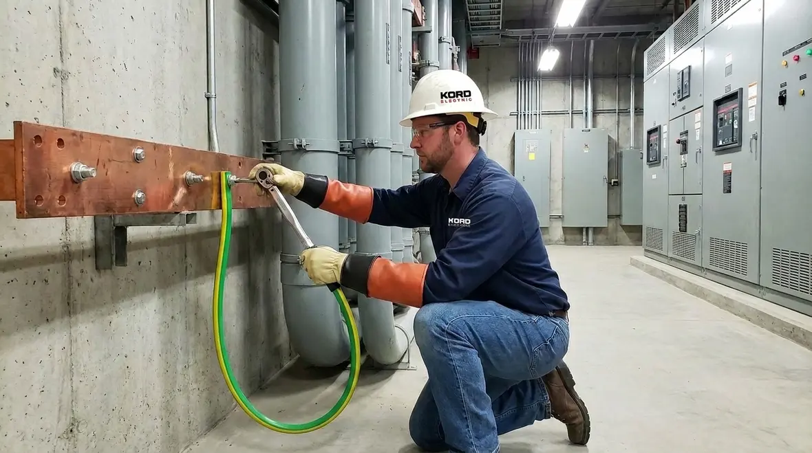
Section 270.70 does not exist to make paperwork thicker. It exists because higher voltage systems create higher risk when grounding and bonding fail. When a fault occurs, electrical energy must travel a safe path to earth. If the electrode connection methods above 2 kV are wrong, that path can become resistive, intermittent, or simply unsafe. As a result, equipment can experience damaging voltage rise, touch potential can increase, and protective devices may behave unpredictably.
We also note something that facility owners often miss: grounding is not just about a conductor reaching a ground rod. Instead, it is about the connection quality and the electrical performance of the entire grounding path. This means materials, installation method, and connection integrity all matter together. In other words, you cannot “wing” a bonding connection and expect the system to behave like nothing happened.
NEC electrode connection methods 2 kV in plain operational terms
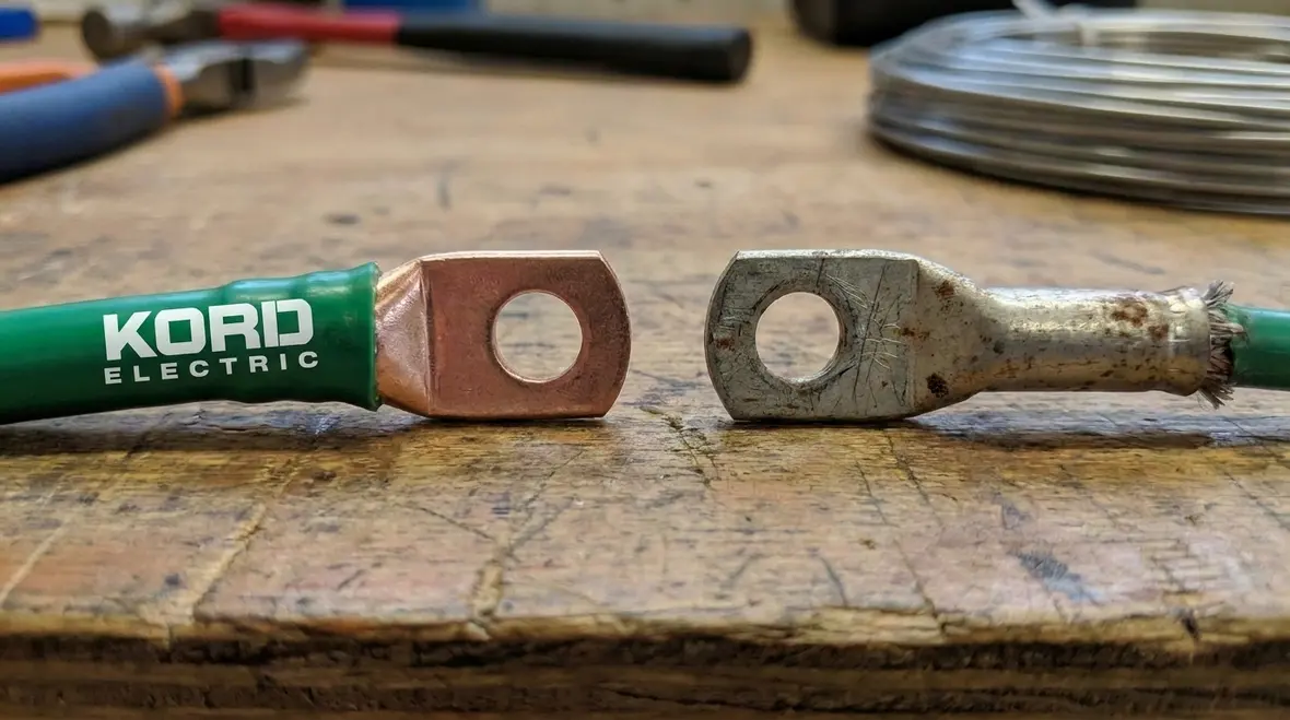
When the system exceeds 2 kV, the NEC electrode connection rules become more specific. Our expert service staff explains it like this in walkthroughs at major property buildings: once voltage climbs, the electrical environment becomes less forgiving. Therefore, the connection between the grounded system and the electrode must support reliable fault current handling and safe energy dissipation.
Practically, we see three recurring goals across installations that meet the NEC electrode connection methods 2 kV intent. First, the connections must provide a low impedance path. Second, the connection method must withstand mechanical stress and long term corrosion conditions. Third, the installation must maintain continuity over time, not just on the day of commissioning. So we build our inspection checklists around those three goals, because they catch issues that “visual only” reviews miss.
Material, size, and connection integrity: where projects win or fail
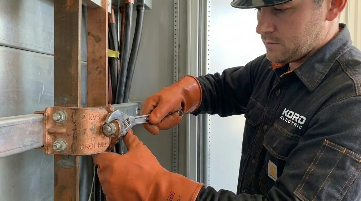
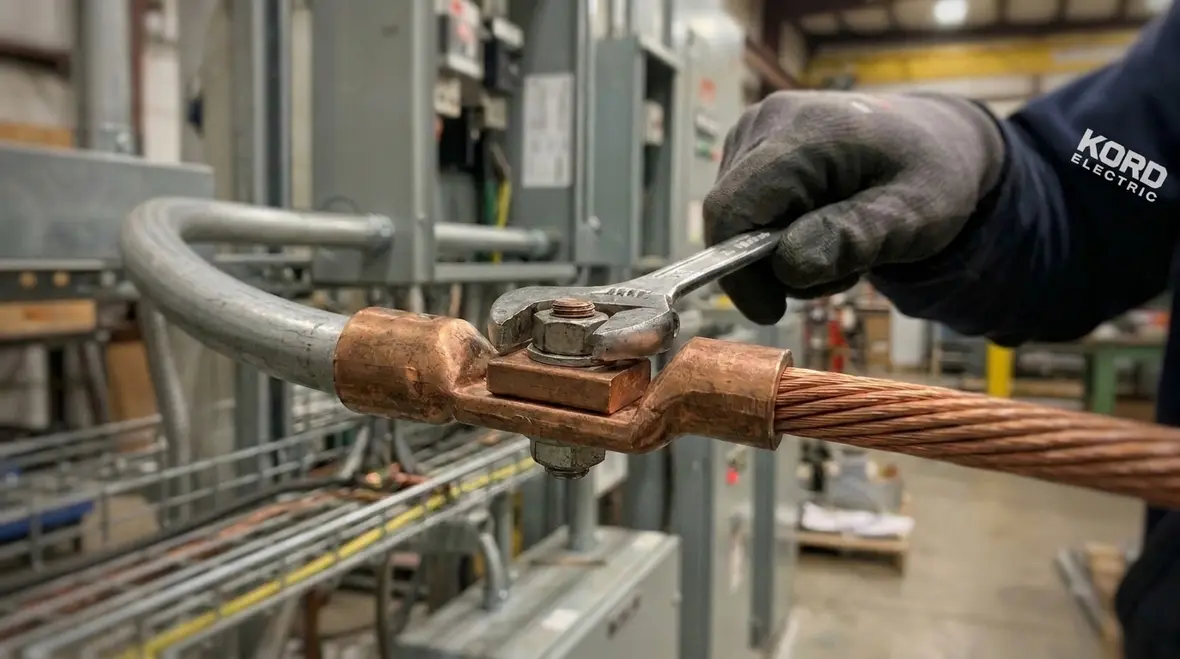
In the field, most grounding problems do not start with the big idea. They start in the small details, and then the small details start to compound. For example, if the conductor material does not match the connection design, or if the installer uses a method not intended for the voltage class, the connection can degrade faster than expected. Even when a bond looks solid, it can still create unwanted resistance if the contact surface preparation or termination quality falls short.
Our technicians often emphasize that connection integrity means three things working together: correct conductor sizing, correct termination technique, and correct environmental protection. Transitioning between metals, choosing terminations, and controlling corrosion risk all matter because commercial and industrial environments can be harsh. Think humidity, airborne contaminants, and vibration from nearby equipment. Consequently, a connection that survives week one can still fail after months if the design and workmanship do not match the real setting.
Also, we recommend that teams document the grounding path like they document the electrical one line. That documentation makes future troubleshooting faster and reduces the chance of “mystery changes” after renovations. It is less dramatic than a disaster, but just as real. Like Batman, we prefer prevention.
Installation workflow we use for compliant electrode connections
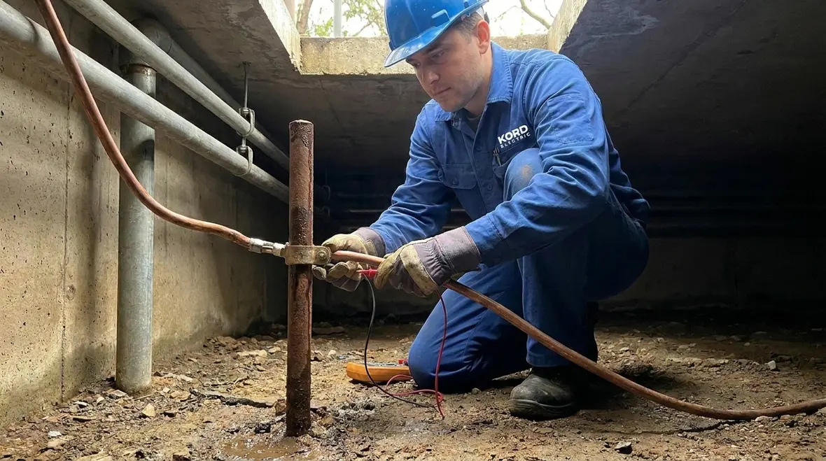
Because our focus stays on commercial and industrial facilities and major property buildings, we follow a workflow that supports both compliance and uptime. We start by reviewing the project plans and grounding system design intent. Then, we verify whether the electrode connection requirements apply based on system voltage and the installation context. After that, our expert service staff coordinates with electrical contractors and facility teams so the grounding work matches the schedule and access constraints.
Next, we inspect how the electrode connection method is planned to be executed. We look at routing, conductor protection, bonding points, termination approach, and exposure risks. Then we verify the actual installation during and after work. Finally, we confirm continuity and perform checks that support safe operation. In practice, we treat commissioning as a process, not a single moment. That way, if a change happens during construction, we catch it before it becomes a long term problem.
Yes, we still see projects where someone “just swaps a fitting” because it looks close enough. However, we remind teams that grounding is not a game of close enough. It is a safety system.
Inspection and verification: how to prove the connection works
Verification helps ensure that electrode connections above 2 kV perform as intended, not just as installed. While code compliance requires methodical adherence to the NEC requirements, facility teams also benefit from practical confirmation steps. For that reason, we guide owners toward verification that covers both the physical and functional aspects of the grounding system.
First, we check that the connections match the design intent and installation method required for the voltage range. Then we examine workmanship details such as cleanliness at connection points, secure terminations, and protective treatment where needed. Finally, we perform testing and continuity verification in line with standard industry practice and project requirements. If you only inspect the appearance, you miss the hidden issues that show up as resistance later.
We also coordinate with maintenance teams so they understand what they should monitor over time. In major property buildings, grounding connections often sit in hard to reach areas. Therefore, we emphasize access planning during design, and we recommend inspection intervals based on environmental conditions and operational risk.
Related code context: keeping NEC grounding consistent with safety goals
Grounding rules do not stand alone. NFPA 70 works as a system, and electrode connections must align with the broader safety goals of the NEC. For example, bonding and system grounding practices must support fault protection, reduce shock risk, and maintain stable reference points for the electrical system. As a result, when teams treat grounding as a standalone “check box,” they often create mismatches between components.
Kord Electric supports teams by translating these requirements into construction-ready guidance. We also encourage facilities to align their documentation and labeling with the intended bonding and grounding scheme, because confusion drives mistakes. If someone later cannot trace the grounding path, they might repair it incorrectly. And repairs matter, because a repair is just a new installation with different expectations.
For deeper reading on the NEC framework and how facilities should approach grounding and related safety topics, many teams also reference resources from Kord Electric and Kord Fire, including code-focused explainers on their sites. For example, you can explore their detailed guide on understanding NFPA 70 and the National Electrical Code for 2026, which connects high level rules with field conditions in commercial and industrial buildings. For fire and life safety cross awareness, firepump related organizations like FirePumps also publish practical guidance that supports safer facility operation. We treat these as helpful context, and we then apply the exact requirements to the project in front of us.
How NEC electrode connection methods 2 kV support real facilities
In day-to-day operations, NEC electrode connection methods 2 kV show up less as “code language” and more as whether equipment behaves calmly when something goes wrong. When a fault travels through a properly designed grounding system, protective devices operate the way coordination studies expect. Breakers open, relays respond, and downstream equipment does not become an unplanned test subject. When grounding is sloppy, that same event can produce unexpected voltages, nuisance trips, or damage that only becomes obvious after the fact.
For facilities that operate around the clock or support critical loads, these differences matter. A process line, data environment, or high density tenant building may tolerate a brief interruption, but it will not tolerate repeated mystery faults. That is why we encourage owners to treat grounding and electrode connections as reliability infrastructure, not just compliance infrastructure. When the NEC electrode connection methods 2 kV are applied correctly, they reduce the odds that a fault will turn into a multi-day investigation with uncomfortable meetings.
Coordinating grounding with broader electrical planning
Above 2 kV, electrode connections interact with transformers, switchgear, medium-voltage feeders, and protection schemes in ways that demand deliberate planning. When Kord Electric reviews a project, we do not isolate grounding from feeder sizing, equipment placement, or protective device settings. Instead, we look at how the grounded system will behave during faults, switching events, and maintenance operations, and we confirm that electrode connections support that behavior instead of undermining it.
For example, when new equipment is added or existing gear is upgraded, we often recommend revisiting how grounding electrodes are connected and how those connections interact with bonding jumpers, neutral terminations, and metallic raceways. This keeps the facility from slowly drifting into a configuration where part of the system “sort of” follows the NEC while another part follows old habits. Over time, that drift is where surprises tend to hide.
When projects touch higher-voltage distribution, we also encourage teams to align grounding work with broader electrical system design planning. That might mean coordinating with studies that look at fault current, selective coordination, and arc flash, or tying grounding improvements into building-wide efforts like preventive electrical maintenance so the system gets checked routinely instead of only after an event.
FAQ: NEC electrode connections above 2 kV
Connecting electrode work with Los Angeles County electrical services
For many owners, electrode connections above 2 kV are just one part of a broader power strategy. When Kord Electric supports a site, we often link grounding improvements with services that keep the rest of the system dependable, from troubleshooting stubborn issues to planning upgrades that match how the building is actually used. If your facility is in Southern California and you want one team to handle both the higher voltage details and everyday power needs, it helps to work with a contractor whose crews already understand complex commercial and industrial environments.
That is where Kord Electric’s Los Angeles County electrical services come into play. The same technicians who understand NEC electrode connection methods 2 kV and above can also support work like system design, downtime prevention, electrical troubleshooting, and data center power strategies. This keeps your grounding decisions aligned with real-world operations instead of living on an isolated drawing set nobody revisits.
Conclusion: bring your grounding design to Kord Electric before it becomes a problem
If you operate a commercial or industrial facility and your system involves conditions above 2 kV, you cannot treat electrode connections like a minor detail. At Kord Electric, our technicians and expert service staff help you apply NFPA 70 Section 270.70 correctly, verify safe installation practices, and document the grounding path for long term reliability. Contact us to review your project, plan inspections, and reduce surprises during commissioning. Let’s make sure your grounding system performs like it should, not like a guess dressed up as engineering.
When you are ready to move from “we think it is grounded” to “we know it is grounded correctly,” bring your plans, your existing infrastructure, and your questions to our team. We will walk through how NEC electrode connection methods 2 kV apply to your facility, what needs to change, and how to make those changes without turning your building into a test lab. The goal is simple: grounding that behaves the same way on your busiest day as it does on your quietest.