NEC AC GEC Sizing 2 kV Under NFPA 70 270.66
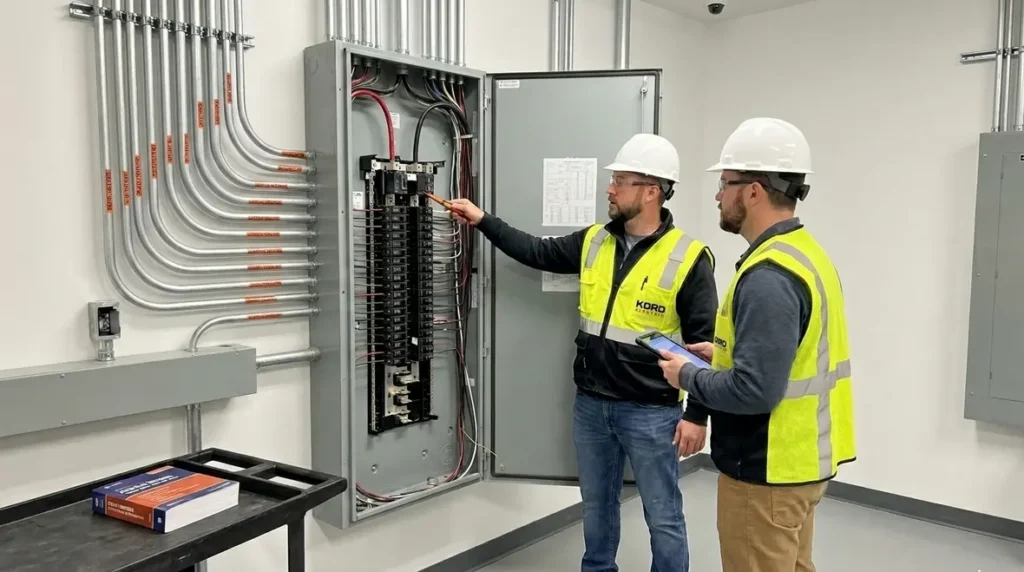
When teams face the job of NEC AC GEC sizing 2 kV at higher voltages, they often meet confusion, not clarity. Yet, the method is not mystical. It is defined in NFPA 70 Section 270.66, and it focuses on how the equipment grounding conductor, also called the AC ground fault equipment grounding conductor, must be sized when the system is over 2 kV. At Kord Electric, we handle this work for commercial and industrial facilities, and for major property buildings where downtime and mistakes cost real money. And yes, we know that reading code sections can feel like watching paint dry, but our expert service staff turns it into a plan you can build, inspect, and trust.
NFPA 70 270.66 and what it changes for systems above 2 kV
NFPA 70 Section 270.66 sets the rules for sizing the AC GEC when the system is over 2 kV. In simple terms, it tells us how to match the grounding path to the fault energy and the behavior of the electrical system during a ground fault. That matters because a ground fault is not a polite event. It moves fast, and it can create heat and stress inside conductors and connections.
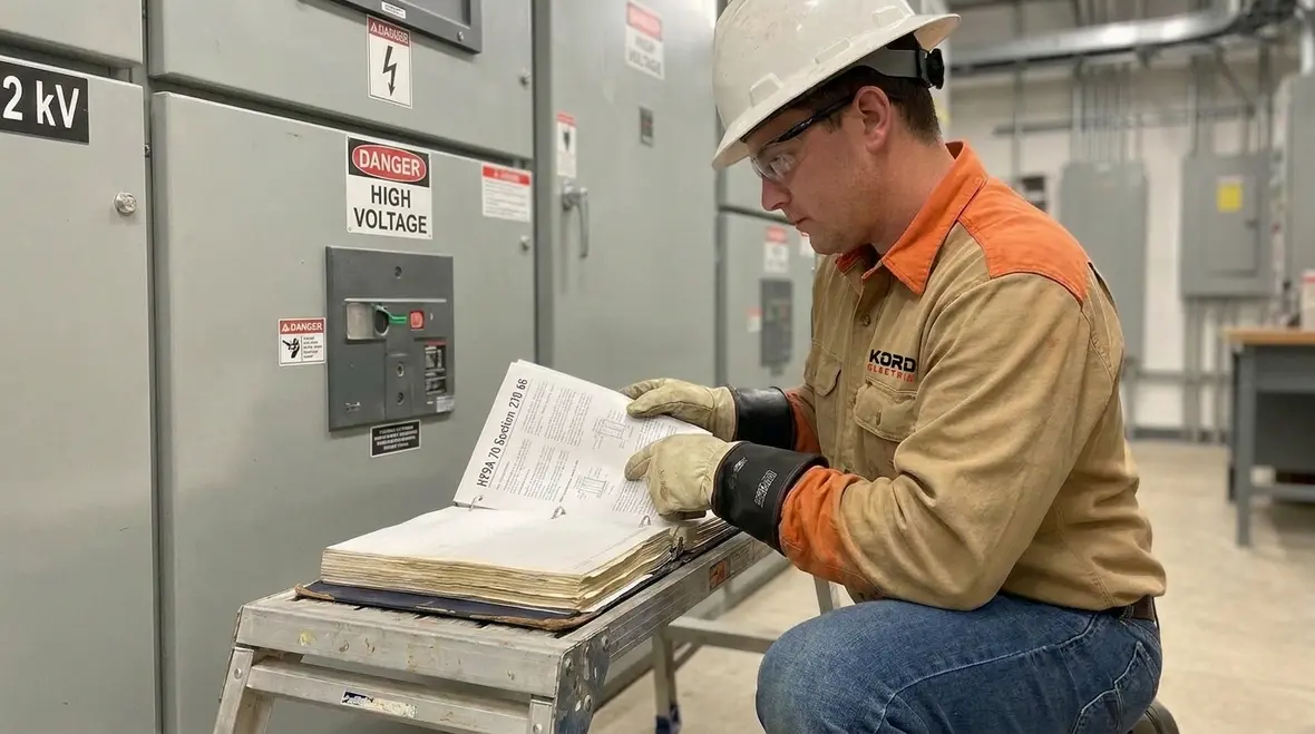
When a facility includes switchgear, transformers, or medium voltage distribution, the design team needs a safe path that can carry fault current long enough for protective devices to clear. Therefore, we do not treat AC grounding as a guess. We size it based on the code method, and we verify the full setup, not just a single wire size on paper.
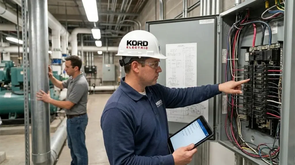
At Kord Electric, our technicians and expert service staff explain the “why” as they go. We walk stakeholders through how 270.66 differs from lower voltage grounding approaches and why it aims to protect equipment, keep conductor temperatures within allowed limits, and help ensure the fault is cleared by the protection scheme.
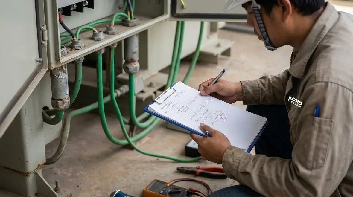
How the AC GEC works in a real commercial power system
In a typical commercial or industrial facility, the electrical system rarely sits still. It grows, it gets modified, and it gets reconfigured. Additionally, different loads cycle throughout the day. As a result, ground fault behavior becomes part of the overall safety design, not an afterthought.
During a fault, the electrical system needs a low impedance return path so that the fault current reaches levels that protective devices can detect. Then the breakers and relays act. If the AC ground fault path is too small, it heats excessively, voltage rises can increase, and the protective devices may not clear within expected time limits. That is not just a theory. It shows up in inspections, commissioning notes, and sometimes post event reports that nobody wants to write.
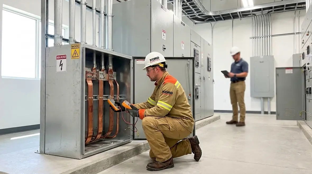
Because our team supports major property buildings, we also consider practical installation constraints. We think about routing, termination quality, and the environment around switchgear and medium voltage equipment. After all, a conductor that is correctly sized on the drawing still fails if the terminations are sloppy, like a movie prop with no weight.

NEC AC GEC sizing 2 kV: the core method under 270.66
For systems over 2 kV, the code method in 270.66 ties the AC GEC sizing to fault clearing requirements and thermal effects during fault conditions. In effect, the size must withstand the heat rise caused by fault current until the system clears. Therefore, you use the code rules to calculate a conductor area and select a conductor size that meets the required limits.
In practice, we approach it in a sequence that helps teams avoid mistakes. First, we confirm the system voltage class and the applicable section triggers. Then we gather the protection data and fault clearing time. Next, we calculate based on the conductor material options permitted by the code method and the installation conditions. Finally, we confirm that the proposed conductor works with the equipment grounding plan for the entire facility.
Our expert service staff explains each step in plain business terms. We do not rely on jargon, because teams need to approve decisions quickly. When others see the reasoning, they move from “I hope it passes” to “I understand why it passes.” That is the difference between a code compliance job and a safety solution.

Selecting conductor types, materials, and installation conditions
Even when the calculation is correct, the final result depends on installation details. Conductor material, insulation, and exposure conditions influence how the conductor handles fault heat. In addition, equipment layout affects what is feasible to run and how connections are made.
Commercial and industrial facilities often include medium voltage compartments with limited routing space. Consequently, design teams must coordinate between electrical and physical constraints early. Kord Electric supports that coordination. We help ensure the AC GEC sizing 2 kV decisions align with how the conduit, cable tray, and terminations will be built.
We also take a hard look at termination quality. A properly sized conductor with poor lugs, loose torque, or incorrect surfaces behaves like a watch with the battery installed upside down. The system still has parts, but it does not do the job. Therefore, our technicians apply consistent installation standards and confirm details before close out.
Coordination with protective devices and fault clearing strategy
Code-based sizing does not float in a vacuum. It works alongside the protection scheme. Protective relays, breaker clearing times, and fault detection settings decide how long the fault current flows. Then that duration drives the thermal stress the AC ground fault path must handle.
So, we connect the dots. We ask for the relay settings basis and the equipment clearing characteristics. Next, we compare that to the ground fault clearing assumptions used by the design calculations. If the protection scheme changes during commissioning, we update the basis and confirm the conductor sizing still holds.
In the field, that coordination prevents nasty surprises. For example, a facility might plan for one clearing time, then later update relay coordination to improve selectivity. That update can change the time window for fault clearing. As a result, we treat AC grounding design as part of the protection review, not a separate task that gets left behind.
And yes, we sometimes hear the classic line, “Don’t worry, it’s basically the same.” Electricity is not impressed by “basically.” Our team makes sure the numbers stay consistent.
Common mistakes we see during review and commissioning
We learn a lot from reviewing submittals and participating in testing. And across projects for commercial and industrial sites, certain errors show up again and again.
- Using the wrong basis for conductor sizing when the system voltage is over 2 kV
- Missing updates when relay settings or clearing times change after design
- Overlooking installation factors that affect allowable conductor performance
- Relying on generic assumptions instead of the specific facility equipment and grounding scheme
- Ignoring termination details that reduce the real performance of a properly sized conductor
To keep things smooth, our expert service staff explains how the calculations link back to equipment behavior. That means fewer back and forth emails, fewer change orders, and less time spent trying to interpret code like it is a hidden treasure map.
NEC guidance resources and how we use them
Kord Electric aligns our field approach with the NEC framework and the way the code explains requirements for grounding and fault protection. We use trusted references, and we lean on local expertise and consistent jobsite practice. For a broader code discussion that supports the way teams think about NFPA 70 and NEC requirements, we often point clients to our educational materials on Kord Electric’s site and Kordfire resources.
If you need context on how the National Electrical Code works at a high level, our team also supports readers through practical explanations found on our related pages, including content like “Understanding NFPA 70: The National Electrical Code Explained for 2026” on the Kord Electric blog, as well as Kordfire resources. You can explore more about how NFPA 70 shapes real facilities at https://kordfire.com/nfpa-70-all-about-the-national-electrical-code-nec/ and general platform info at https://kordfire.com.au/, then return to project specific planning with our technicians and expert service staff.
And if your facility includes fire pump systems and related life safety electrical design, you may also find value in industry context at https://firepumps.org/, especially when coordinating power systems across life safety loads. We do not just “share links.” We use them to help teams ask better questions internally, so when we sit down with the contractor, engineer, or commissioning agent, we move faster and we align on the same code intent.
Quick comparison: what changes from lower voltage grounding
When teams used to lower voltage grounding methods, they often assume the same rules carry forward. However, for systems above 2 kV, NFPA 70 Section 270.66 changes the sizing path and how fault heat and clearing time drive the requirement. Below is a simple view we use during design coordination.
| Lower voltage context | Over 2 kV context under 270.66 |
| Teams may rely on common equipment grounding assumptions | Teams must size the AC ground fault equipment grounding conductor based on fault clearing and thermal limits |
| Routing and terminations still matter, but fault heat behavior assumptions often differ | Fault duration and protective clearing strategy strongly influence conductor sizing outcomes |
| Commissioning focuses on continuity and basic compliance checks | Commissioning also validates that protection coordination matches the sizing basis |
FAQ: AC GEC sizing for systems over 2 kV
Conclusion and call to action
Kord Electric helps commercial and industrial facilities get grounding right for systems over 2 kV, so safety stays real and compliance stays clean. Our technicians and expert service staff translate NFPA 70 Section 270.66 into a practical plan that connects calculations, protection timing, and field installation. If you are reviewing submittals, planning commissioning, or updating a facility’s medium voltage gear, reach out to Kord Electric. We will help you confirm the approach early, avoid rework, and keep your project moving with calm confidence.
For facilities across the region, our Los Angeles County electrical services bring together code-aware design, precise installation, and responsive support, so your grounding, protection, and power quality all work as one system instead of separate checkboxes.