NFPA 70 Section 315.60 NEC MV Conductor Ampacities Explained
In commercial and industrial work, we do not guess when it comes to NEC MV conductor ampacities. We start with the ampacity rules that NFPA 70 Section 315.60 sets for medium voltage conductors, then we confirm the numbers match the installation conditions on site. That means we account for what the system is, how the cable runs, and how heat will move through the space. And yes, the details matter because heat does not care that a project manager is in a good mood.
To keep things calm, our technicians at Kord Electric translate the NEC language into practical decisions. For example, we treat derating factors, termination limits, and installation temperature effects like they are part of the blueprint, not a later surprise. Next, we will walk through what Section 315.60 is really trying to protect you from, and how we apply it in the field.
NFPA 70 Section 315.60 and NEC MV conductor ampacities, explained for commercial facilities
Medium voltage installations sit in a space where current, insulation strength, and heat management all intersect. That is why we start every planning conversation with the NEC rules that apply to your specific system, not with a generic table. NFPA 70 Section 315.60 gives us the framework for how to think about conductor ampacity in that environment, and it links those numbers to the way conductors are actually installed.
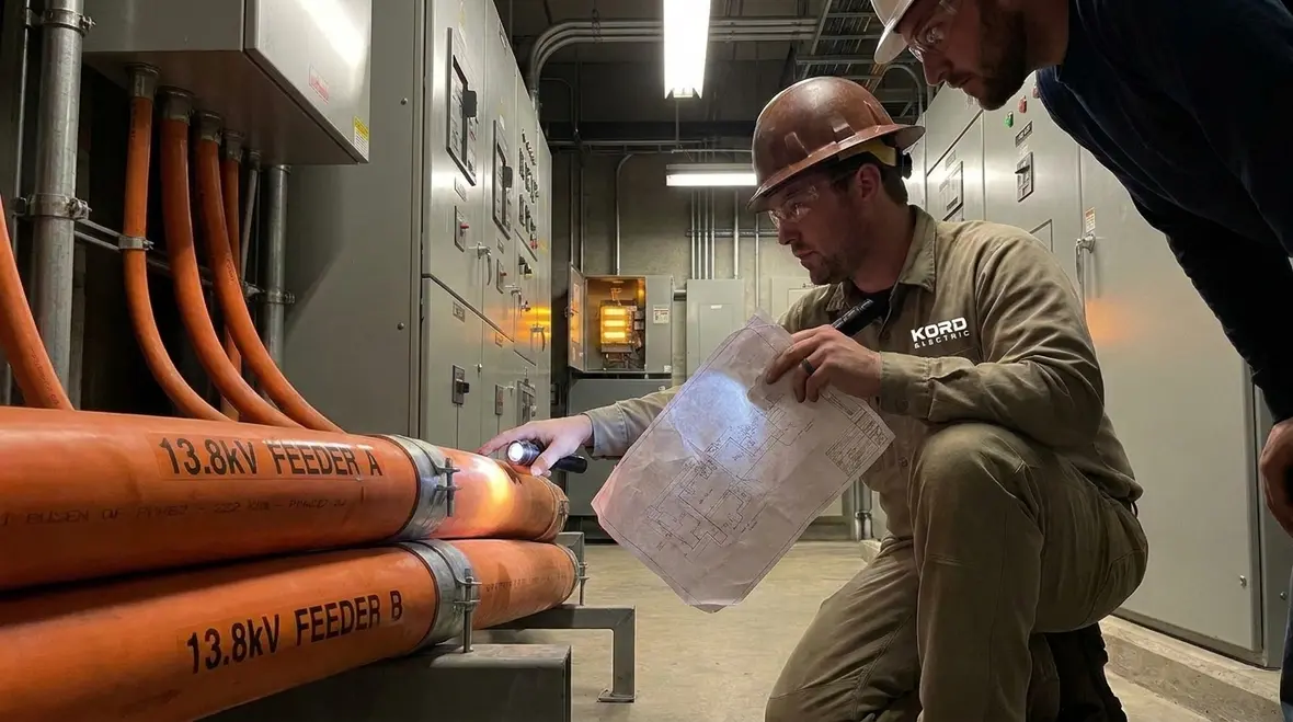
In commercial and industrial facilities, that framework becomes the bridge between design intent and field reality. We tie Section 315.60 back to the broader NFPA 70 picture so your team can see how ampacity rules connect to conductor sizing, feeder ratings, and grounding and bonding strategies. For a deeper overview of how the NEC shapes medium and low voltage work, many facility teams also review our related resource Understanding NFPA 70: The National Electrical Code Explained for 2026, then circle back to section-specific topics when they are ready to plan real projects.
Why Section 315.60 matters when the voltage is medium
Most people think the NEC is about rules for wires and boxes. In reality, it is about preventing thermal stress and keeping conductors in a safe operating range. Therefore, NFPA 70 Section 315.60 focuses on MV conductor ampacities for medium voltage conductors, and it ties those ampacity values to the way the cable is installed and used.
When a conductor carries current, it creates heat. Over time, that heat can affect insulation life and connection integrity. Consequently, the code does not just hand out numbers; it pushes you to apply the numbers correctly. If you overshoot the ampacity, you may not fail on day one, but the risk creeps in like a villain who reads the fine print.
At Kord Electric, our expert service staff reviews the full path, not only the nameplate rating. We look at conductor type, insulation, ambient conditions, and how the system connects at terminations. Then we document the assumptions, so your team does not have to rely on memory or coffee. Because in commercial and industrial facilities, the electrical room is not a place for guesswork.
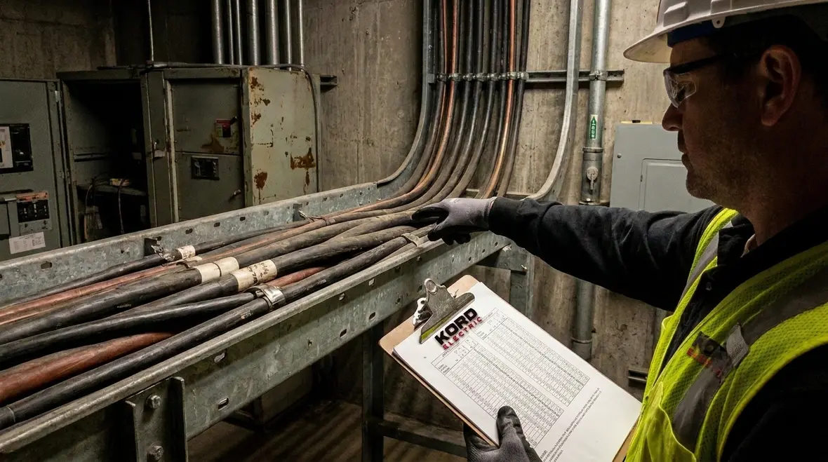
We also connect Section 315.60 to other NEC sections that shape project scope, such as requirements around minimum feeder ratings, grounding, and service supplied systems for higher voltages. That way, your medium voltage planning does not happen in isolation. It lines up with feeder minimums, grounding electrode expectations, and application scope, so inspectors see one coherent story instead of a handful of disconnected drawings.
What ampacity means in the field, not just on paper
Ampacity is the maximum current a conductor can carry under specified conditions without exceeding safe temperature limits. However, in real installations, the “specified conditions” are never identical to a one line example. For that reason, we treat ampacity as a system result, not a single number from a table.
First, we identify the medium voltage system design, including how the conductor will run and what the operating duty cycle looks like. Then we compare those conditions to the code requirements that govern allowable conductor temperature rise. After that, we check related limits such as terminations and equipment ratings. If equipment cannot accept the current the conductor could theoretically carry, the equipment becomes the limiting factor.
Our technicians explain this clearly to facility teams, because understanding is how you avoid rework. Also, if you are used to low voltage rules, medium voltage planning feels like a different game. You might say it is the same sport, but the stakes are higher and the referee is stricter.
For major commercial buildings, this field perspective on ampacity also shapes how we approach service supplied grounding, feeder minimums, and specific purpose loads that ride on top of medium voltage infrastructure. By treating ampacity as a real-world outcome, not an abstract number, we help owners avoid uncomfortable surprises when new equipment comes online or when inspections drill into how conductors are actually being used.
How derating and installation conditions change the numbers
Even when the design uses code based values, the final allowable current may be lower due to adjustment and derating conditions. Therefore, we focus on what changes the thermal profile of the cable. Common factors include ambient temperature, the number of current carrying conductors, and how conductors share raceways or cable trays.
Next, we look at heat dissipation. If the installation traps heat or restricts airflow, the conductor temperature can rise faster. Consequently, the ampacity can require adjustment. In commercial and industrial facilities, this becomes especially important around densely loaded areas like main switchgear rooms, motor control zones, and data or process spaces.
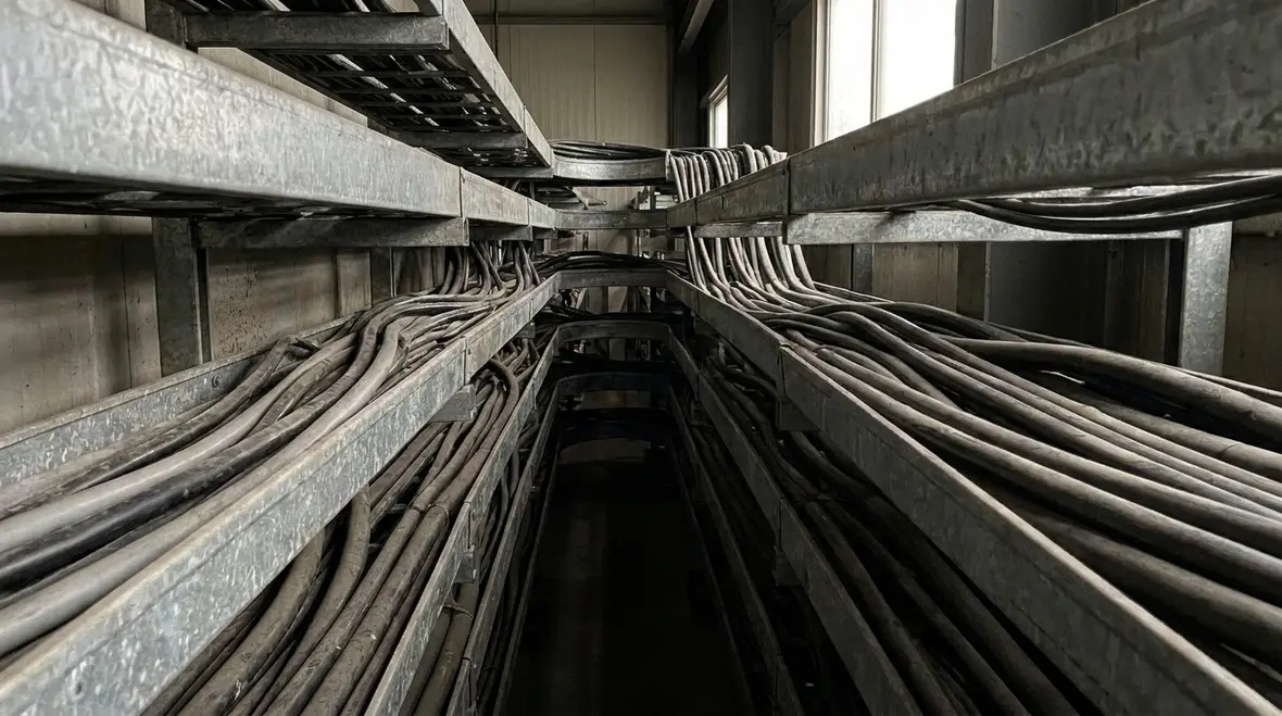
At Kord Electric, we do not treat these as theoretical concerns. We walk the route, confirm the layout, and then apply the NEC logic to the actual installation. Then we help stakeholders understand why the final current limit may differ from the initial table value. If you have ever seen a cable tray that looks like it grew there, you know why we verify instead of assuming.

Derating also intersects with load calculation methods, specific purpose circuits, and feeder sizing. When we help teams apply NEC MV conductor ampacities, we cross check the derating math against the way feeders, services, and grounding paths are planned. That cross-check keeps projects from painting themselves into a corner where a future load increase or layout change suddenly exposes hidden ampacity limits.
Terminations, equipment ratings, and why connections can limit ampacity
People often focus on cable ampacity and forget that terminations and splices must also handle the current safely. Even if the conductor is rated for the design load, the connection point may not. That is where work quality and product selection become critical.
Additionally, medium voltage systems rely on proper installation of terminations, stress control components, and insulation interfaces. If those parts do not meet the application requirements, thermal performance and reliability drop. Therefore, our approach blends code based sizing with disciplined field installation practices.
Our expert service staff explains the connection logic during planning and during commissioning. We do this so owners and facility leads can make informed decisions before installation starts. It also helps prevent the classic situation where everyone thinks the wire is fine until the heat marks show up like a warning label from the universe.
We also check that medium voltage terminations align with broader NEC expectations for service grounding, feeder minimum ratings, and equipment coordination. When connections and equipment ratings match the conductor capacity, the whole system operates in a safer, more predictable temperature band instead of running at the edge of what the weakest link can handle.
NEC MV conductor ampacities workflow we follow for major buildings
When we support commercial and industrial facilities, our process stays consistent. We start with the design documents, then we translate them into a conductor and installation plan that follows NEC intent. After that, we verify the plan in the field and document the results. Here is the workflow we use at Kord Electric.
1) Review the system and conductor details
We confirm voltage class, insulation type, conductor construction, and expected loading. Then we identify the conductor arrangement and routing conditions.
2) Apply code ampacity rules
We use NFPA 70 NEC requirements, including NFPA 70 Section 315.60, to set the allowable basis. Then we apply any needed adjustments based on installation conditions.
3) Check derating and thermal limits
We evaluate ambient temperature, conductor grouping, and heat dissipation. If conditions demand it, we adjust allowable currents accordingly.
4) Verify terminations and equipment ratings
We compare conductor limits against termination ratings and connected equipment limitations. If any part of the chain restricts current, we size to the tightest limit.
5) Document assumptions for the owner and inspectors
Our technicians record the basis of design and the installed conditions that support the final ampacity decision.
6) Support testing and commissioning
We help validate performance and we address issues early, so the system starts strong and stays strong.
By the time the system energizes, the numbers have already been tested against reality. And that is how we keep projects on schedule and safety on point.
For large facilities, we often pair this workflow with NEC planning resources that explain scope, wiring fundamentals, and application requirements. That way, facility leaders see how conductor ampacity decisions line up with feeder sizing, grounding systems, and remote control circuits that all live inside the same project.
Common mistakes we see during medium voltage conductor sizing
Errors in medium voltage projects rarely come from one big mistake. More often, they come from small misunderstandings that pile up. For instance, a design team may pick a conductor size that matches a table value but ignores derating factors. Or they might assume the cable tray or duct layout matches a generic example, even though it does not.
Another frequent issue involves terminations and splice selection. If the termination kit does not match the conductor rating, installation standard, or insulation class, the electrical performance and heat tolerance can suffer. Also, crews sometimes treat “rated” as “compatible,” and that is where trouble begins.
We address these problems by doing what others skip: we connect the design intent to the installation facts. Our technicians and expert service staff explain the “why” to keep teams aligned. So instead of arguing about numbers, everyone understands the logic and the constraints. It is like having the answer key, but without the drama of a surprise quiz.
We also clarify how medium voltage conductor sizing interacts with NEC MV conductor ampacities, feeder minimum ratings, existing load calculations, and specific purpose load rules. When project teams see how these pieces fit together, they are less likely to overlook a detail that later shows up as an overloaded connection or an inspection comment written in very direct language.
FAQ about NFPA 70 Section 315.60 and medium voltage ampacity
Get the ampacity right before energizing the system
When we handle medium voltage projects for commercial and industrial facilities, we treat NFPA 70 Section 315.60 as a safety and performance guide, not paperwork. Our technicians and expert service staff verify the conductor sizing logic, apply installation adjustments, and confirm termination and equipment limits. That reduces risk, supports smoother inspections, and keeps your system within safe operating temperatures. If you are planning a build, upgrade, or major property modernization, contact Kord Electric and let us help you get it right the first time.
For facility leaders in Southern California, that planning often includes coordinating medium voltage decisions with broader building work such as power distribution, grounding, and upgrades across large campuses. Our Los Angeles County electrical services team supports that coordination, aligning NEC MV conductor ampacities with the feeders, services, and protection that keep entire properties running safely and consistently.
If you want to explore how these ampacity decisions fit into the wider NEC framework, you can also review our educational resources on NFPA 70 that walk through scope, application requirements, and wiring fundamentals for 2026. Then, when you are ready to move from learning to building, our field teams connect the rulebook to real conduit, raceways, and switchgear stands inside your facility.