Kord Electric Explains NFPA 70 Section 690.32
In commercial and industrial buildings, solar systems run on real rules, not vibes. Within the first stretch of any well planned design, teams must understand NFPA 70 Section 690.32 PV component interconnections, because it covers how photovoltaic parts connect so power moves safely and predictably. In plain terms, we focus on how modules, inverters, and other system parts link together, including grounding and bonding approaches that help protect people, property, and uptime. And yes, we also want your system to last longer than the average office plant. Our technicians explain these requirements in a way that helps building owners make good decisions, not just sign forms and hope.
Before we go deeper into PV component interconnections, many facility teams like to ground themselves in the bigger picture of the National Electrical Code. For a broader walkthrough of how the rulebook works, you can review our companion guide, Understanding NFPA 70: The National Electrical Code Explained for 2026, which connects the high level code structure to everyday decisions in commercial and industrial buildings.
Kord Electric explains NFPA 70 Section 690.32 PV component interconnections
When facility owners ask what really changes once solar shows up on the roof or in the yard, we start with the connections. NFPA 70 Section 690.32 PV component interconnections focuses on how photovoltaic components link together so current flows the way your design expects, not the way a fault decides. That includes how modules connect into strings, how those strings connect into combiners or DC inputs, and how inverters and related equipment pass power into the rest of the facility.
For commercial and industrial work, we treat those rules as part of a bigger reliability story. Proper interconnections control heat, manage mechanical stress, and keep insulation, connectors, and terminations from becoming unplanned “test points” for failure. Instead of just asking “Does this pass inspection today?” we ask “Will this behave on year ten when the sun, wind, and real operations have done their work?” That is where NFPA 70 Section 690.32 PV component interconnections moves from a paragraph in a book to a practical checklist for uptime.
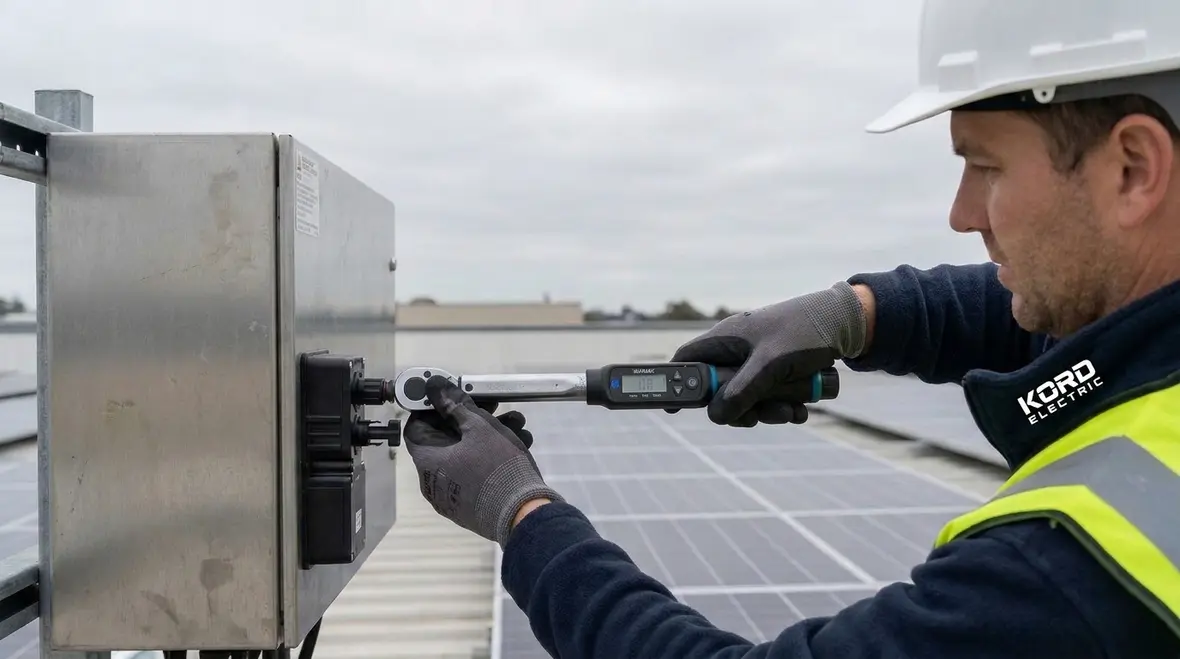
On real projects, that checklist ties into our data-driven design and inspection work. We combine Section 690.32 requirements with connection quality practices similar to those covered in our connection quality resources, so each PV joint, splice, and termination pulls its weight instead of becoming the weak link in your power chain.
Why commercial and industrial solar needs stricter electrical code thinking
Many facilities treat solar like an add on. However, in warehouses, campuses, factories, and major property buildings, the electrical system already carries a heavy load. Therefore, a rooftop PV upgrade must fit into an environment where fault current, switchgear coordination, and emergency power plans already matter. When we review designs, we do not just check boxes. Instead, we connect the code rules to what your staff and your equipment actually experience.
That is also why we lean on NFPA guidance and consistent installation practice. In the real world, loose terminations, poor cable routing, or mismatched components can lead to heat, nuisance trips, and outages that ruin a day and sometimes a whole week. So, when our expert service staff walks the job site, they look for the details that prevent “why did this fail” conversations later.
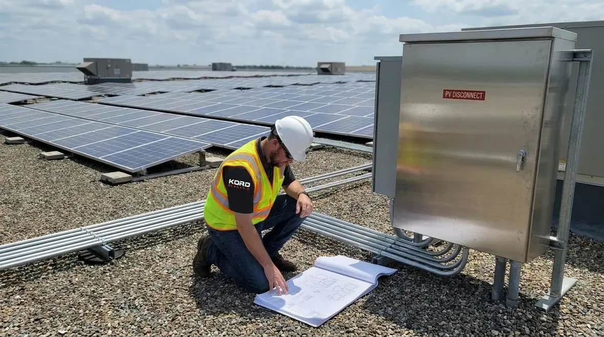
In commercial EV charging projects, data centers, and emergency power designs, we already plan around high uptime expectations. PV should not be the exception that quietly breaks those expectations. By applying the same disciplined NEC thinking to your solar upgrade that we apply to backup power and surge protection work, we help your building avoid surprise downtime that shows up the first hot day the system is actually needed.
What NFPA 70 does for PV systems in 2026 planning
NFPA 70, also called the National Electrical Code, sets minimum safety requirements for electrical installations. When teams plan for 2026 related updates, they need a clear view of how the code organizes conductors, equipment, grounding, labeling, and protection. Then, they can match the PV design to the rest of the facility electrical system.
At Kord Electric, we treat the NEC as a roadmap, not a suggestion. For example, PV systems involve DC power, which behaves differently than typical AC circuits. DC arcs can sustain longer, and that means our approach to disconnecting means, overcurrent protection, and isolation becomes more serious. Additionally, we coordinate these PV circuits with existing panels, transfer equipment, and load centers so your electrical system does not behave like a complicated jigsaw puzzle without the picture on the box.
We also reference our own NEC learning resources, including guides on connection quality and code upgrade consulting, to keep project decisions aligned with current interpretations of NFPA 70. That way, when your facility updates panels, adds emergency power, or scales other systems, the PV design already fits into a consistent, code minded framework.

When you match NFPA 70 Section 690.32 PV component interconnections with the broader NEC structure, it also becomes easier to defend design choices with inspectors, insurance partners, and internal risk teams. Instead of arguing over isolated details, you can point to a consistent pattern of decisions anchored in the 2026 code direction.
How PV component interconnections reduce risk and improve reliability
The heart of the safety story involves how PV components interconnect. Under NFPA 70 Section 690.32 PV component interconnections, the code focuses on connections and related methods so the system maintains electrical continuity and stability under normal operation and fault conditions. This matters for more than compliance. It affects heat, mechanical stress, and the long term durability of your installation.
Our technicians explain it like this. When you connect PV strings and components, you create pathways for current during sun hours. Yet when conditions change, such as shade patterns, weather shifts, or inverter behavior, the system still relies on stable connections. If a termination loosens or a connector mismatches the intended rating, the system can generate more resistance, which can then create heat. Over time, that heat can damage insulation and insulation can become failure. In other words, small connection problems can grow into big operational headaches.
Therefore, we emphasize proper connector selection, correct torque and termination methods, and cable support that reduces strain at the connection points. We also ensure labeling and routing practices support troubleshooting. And when we coordinate PV wiring with the broader facility electrical plan, we help operators isolate issues quickly instead of playing electrical detective for days.
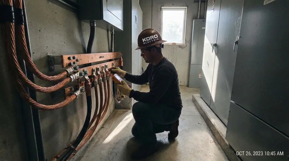
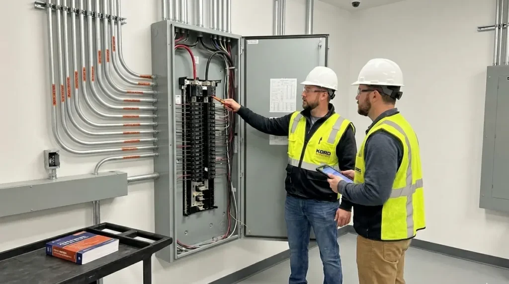
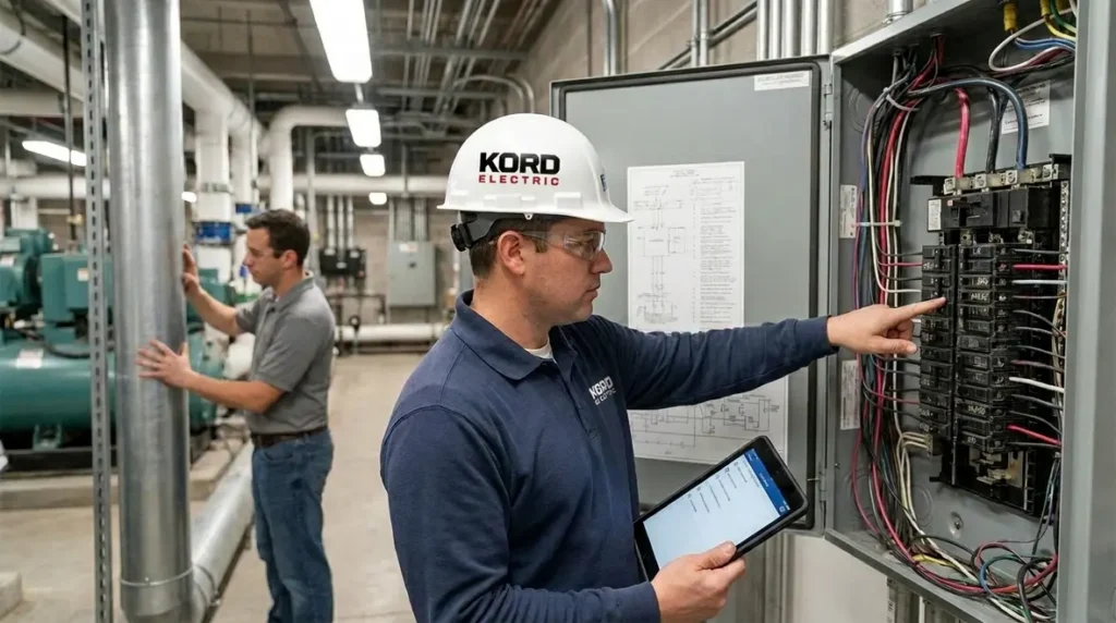
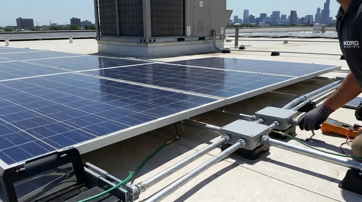
We bring the same discipline we use in our connection quality work into PV interconnections. That means verifying crimp quality, checking compatibility between conductors and lugs, confirming that junction boxes and combiner enclosures match their environmental ratings, and documenting each step so future maintenance teams know exactly what they are looking at.
Grounding, bonding, and how we connect the system to facility safety
Grounding and bonding in PV installations protect people and equipment during faults and surge events. They also help ensure that protective devices operate as intended. When we build a plan for a commercial site, we do not treat grounding as an isolated “solar task.” Instead, we integrate PV grounding with the facility grounding electrode system, existing bonding points, and other equipment grounding paths.
In practice, our team verifies continuity, checks conductor sizing, confirms connection methods, and reviews how the PV system interfaces with inverters and switchgear. We also look at surge protection coordination when it makes sense for the environment. For large property buildings, these steps matter because electrical events can travel through shared infrastructure.
To keep your facility running smoothly, we also help others on the project understand the practical outcome. Proper grounding and bonding can reduce shock risk and limit harmful voltage rise. It can also improve the odds that protective devices trip correctly instead of letting faults linger like a bad tenant who will not leave. And if you are wondering how this fits into broader code thinking, resources that explain the NEC in plain language can help. Our approach aligns with widely discussed NEC training topics, including how PV rules tie into the rest of the electrical system.
Common installation mistakes we prevent in major property buildings
Even strong designs can fail when construction details slip. Here are the issues we see most often on commercial and industrial sites, and how our service staff keeps them from becoming expensive lessons.
- Strain on connectors: Technicians support cables so they do not tug on PV terminations. When cables move in wind or thermal cycles, connections need relief.
- Improper connector pairing: We confirm components match the system design and ratings. Mismatched parts look fine until they do not.
- Inconsistent labeling: We ensure PV circuit identification supports safe isolation during maintenance and emergency response.
- Loose termination or incorrect torque: We follow manufacturer and code minded practices. A loose connection is basically a tiny heater disguised as a connection.
- Routing that ignores protection: We route cables and secure them to protect against abrasion and damage, especially where traffic, construction activity, or harsh weather exist.
Because we work with commercial and industrial facilities, our focus also includes coordination with other trades. We communicate where electricians, roofing crews, and mechanical contractors meet. Then we avoid the classic scene where everyone claims, “We did it the right way,” and the building pays the price later.
Electrical room coordination, fire protection interfaces, and system handoffs
Commercial sites do not run on solar alone. Therefore, we coordinate PV systems with the facility electrical distribution and the safety systems around it. This includes emergency power considerations, critical loads, and how the PV system interacts with inverters and utility service disconnects. We also make sure staff can perform safe shutdown procedures without guessing.
On the fire and life safety side, the PV design must align with the facility safety plan. Many teams use fire pump and fire protection resources to understand system behavior, and those concepts matter when electrical shutdown, monitoring, and emergency response come into the picture. For example, the fire protection design community often emphasizes reliable interfaces and clear system operation. While electrical code rules drive PV installation safety, building safety still depends on how systems hand off information and control.
Additionally, we help property managers plan future maintenance. If you build a PV interconnection and grounding approach that supports safe access and clear identification, you reduce downtime. In the end, that protects revenue and keeps operations stable.
Dual column checklist for PV interconnections and readiness
| What we verify | Why it matters |
|---|---|
| Correct PV conductor and connector compatibility | Reduces resistance and heat at terminations |
| Proper grounding and bonding continuity | Supports protective device response and shock safety |
| Mechanical support and cable routing protection | Limits strain, abrasion, and long term wear |
| Clear labeling for circuits and isolation points | Speeds safe maintenance and emergency operation |
FAQ
Final word from Kord Electric: plan right, operate confidently
When a commercial or industrial facility installs PV, the goal is simple: safe power that runs for years. We help owners and teams interpret NFPA 70 requirements, coordinate the PV electrical plan with the facility distribution, and verify grounding, bonding, and interconnection details that reduce risk. Our expert service staff explains what matters and why, without mystery jargon. If you want a solar install that performs like it should, contact Kord Electric today and let us help you build it right from the start.
For facilities in Southern California that want that support from a team already working across campuses, warehouses, and high value properties, our Los Angeles County commercial and industrial electrical services team stands ready to integrate PV safely into your broader electrical strategy, from initial planning through final commissioning.