NEC Article 240.1 Scope for Overcurrent Protection
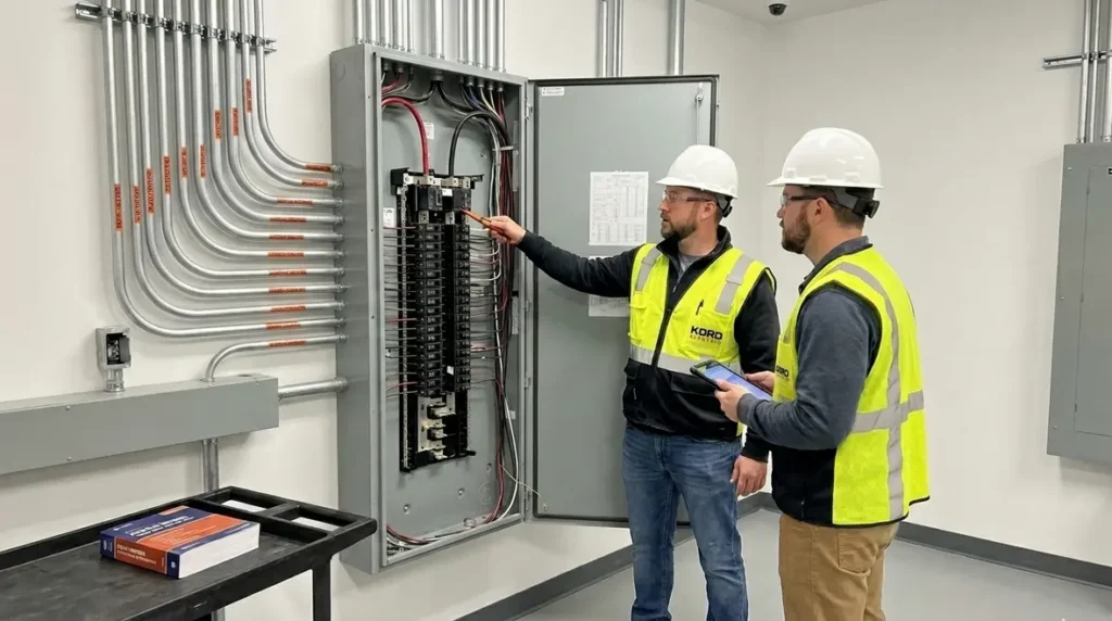
NFPA 70 Section 240.1 sets the stage for Overcurrent Protection, and it defines the scope of NEC Article 240. In other words, it tells us what rules cover protection for conductors and equipment when electrical current goes too high. We explain this because commercial and industrial facilities cannot afford guesswork, whether the project is a multi-tenant building, a distribution room, a pump station, or a large site with varied loads.
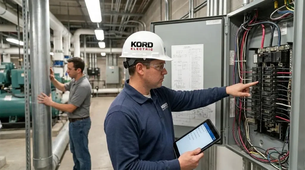
At Kord Electric, we serve commercial and industrial properties and major building projects, and we keep things clear for the people who have to maintain the system after we leave. In our experience, the smartest teams do two things: they plan for faults before they happen, and they ask questions while the design is still flexible. Our technicians and expert service staff walk through the reasoning, step by step, so the final protection scheme makes sense and stays defendable. And yes, we do it with the calm energy of someone who would rather explain things than reset breakers all night. Spoiler: that is exactly what they do.
NEC Article 240 scope, and why it matters in the field
Third person eyes on paper can miss what happens in a plant, a warehouse, or a critical building. The NEC Article 240 scope focuses on overcurrent protection devices and the conditions that require protection. It does not just tell you that protection is “a good idea.” Instead, it links the rules to specific outcomes such as protecting conductors from overheating and protecting equipment from damage due to faults or overloads.
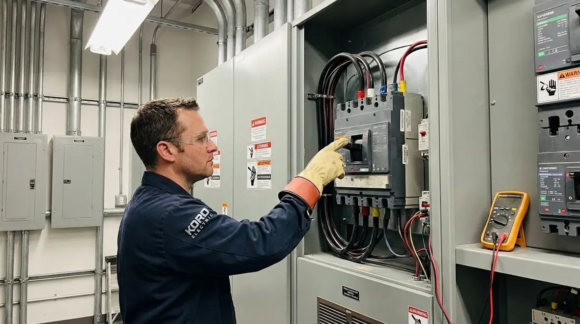
Overcurrent protection also acts like a referee. When current runs above what a circuit can safely carry, a properly selected device interrupts the excess current. Then, equipment keeps doing its job, and the facility avoids unplanned downtime. For commercial and industrial facilities, that means stable operations, safer maintenance, and fewer “why did this happen” meetings that last longer than they should. Transitioning from design to real life, the key is to ensure the device behavior matches the circuit needs under likely fault current and normal load conditions.
Where overcurrent starts: overload, short circuit, and fault current reality
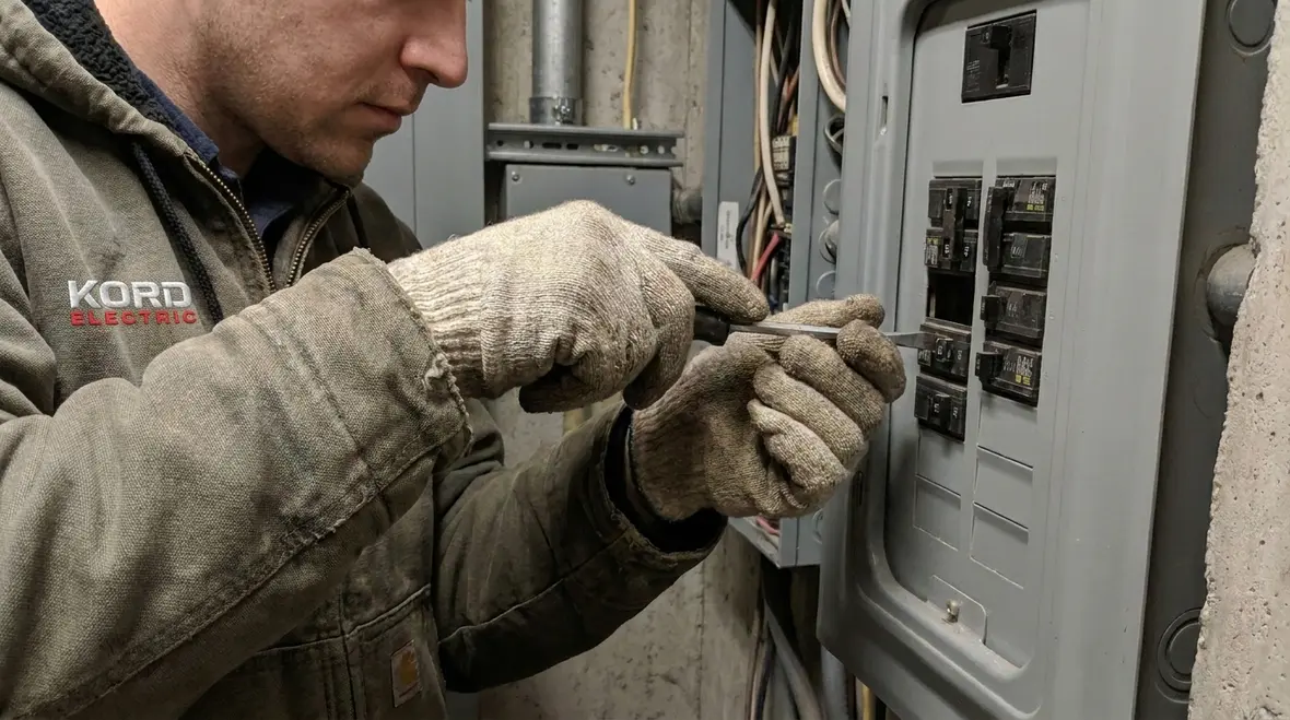
It helps to separate three common causes, because they behave differently. First, overload usually means the circuit carries more current than expected for a sustained period, often from motor loads that draw higher current during production shifts. Second, a short circuit often involves a direct low resistance path, which can rise fast and severely. Third, fault current covers the electrical condition that causes abnormal current during insulation failure or wiring issues.
Then the selection questions start. A breaker that tolerates overload behavior might still need the right interrupting rating for short circuit conditions. Likewise, a fuse may offer excellent protection in certain scenarios but must match the conductor and equipment requirements. Our expert service staff often sees the same pattern: protection devices get installed, but nobody confirms the full coordination story. As a result, the system can trip during normal operations, or worse, it can fail to clear the fault fast enough.
So we encourage teams to think beyond “will it trip.” They should ask whether the device trips within acceptable time frames and whether the circuit returns to service quickly. That is not bureaucracy. It is operational stability.
Device selection that actually fits the circuit, not the brochure
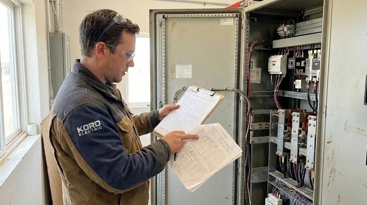
Once the facility identifies the conductor sizes, equipment ratings, and load types, the protection selection becomes a real engineering task. However, many teams still treat it like a plug and play swap. We do not. We guide commercial and industrial projects toward a protection scheme that matches the worst case conditions without turning every outage into a major event.
Here is the practical part. First, the protection device rating must align with the conductor ampacity and the intended load. Second, the system must handle available fault current with an interrupting rating that exceeds the expected fault current at the point of installation. Third, if the design includes multiple devices in series, coordination matters. Coordination means the upstream device should not act before the downstream device. That keeps the smallest area of the facility offline, which is what operations teams want.
To keep this calm and useful, our technicians explain the “why” in simple terms during commissioning and service calls. We do not just say “the rating is correct.” We show how the device clears faults and how that affects continuity of service. In commercial facilities, continuity is money. And if someone tells you the power will be “fine” because it always has been, we gently remind them that physics does not care about confidence. It cares about current and heat.
Coordination and nuisance trips: the hidden cost of bad matching
Coordination sits right at the center of reliable systems. When devices coordinate well, the one closest to the fault clears it. When they do not, the result can include unnecessary shutdowns, equipment stress, and maintenance work that eats up a day like it is a free trial.
Our experience with major property buildings shows that nuisance trips often come from one of three places. First, the protective device may not have the correct time current behavior for the load profile, especially for motors with starting currents and variable production cycles. Second, wiring and terminations may contribute to higher resistance or poor contact, which increases stress. Third, the system may lack a clear coordination study, so the upstream and downstream trips do not line up with the intended clearing path.
So instead of “hoping” the system behaves, we help facilities plan. We look at the devices, the load characteristics, and the expected fault current. Then we align the protection behavior so the system clears faults while keeping normal operations stable. This also supports better documentation, which matters for audits and for the next contractor who touches the same equipment. Transitioning from one maintenance team to another should feel like handing off a story, not a mystery novel.
Case scenarios in commercial and industrial buildings
Now, a realistic view. Kord Electric focuses on commercial and industrial facilities and major property buildings, so the situations we see differ from residential wiring. Here are common environments where Article 240 outcomes show up fast.
Motor driven equipment
Motor driven equipment: In a plant, motors can draw higher current during start. Protection needs to handle that startup without tripping during normal production. Therefore, the chosen device must consider both starting behavior and fault clearing requirements.
Distribution rooms and feeders
Distribution rooms and feeders: Facilities often have multiple feeders feeding critical areas. If devices do not coordinate, a feeder fault can shut down larger sections. In contrast, when coordination works, only the affected branch trips, and the rest of the facility keeps running.
Data and control support areas
Data and control support areas: Even when loads are not heavy like a motor bank, control circuits can be sensitive. If the system relies on protective devices that do not clear faults cleanly, equipment can experience repeated stress. Over time, that stress becomes failures, and failures become unplanned downtime.
In each scenario, our technicians explain what they see during inspection and service work. They also connect the findings to the protection design. That is how teams gain confidence: they understand the pathway from design intent to field performance.
And yes, sometimes someone tries to “solve” protection issues by swapping devices at random. That is like replacing the wrong part of a car and then acting surprised it still won’t start. It might look like action, but it rarely improves safety or reliability.
Documentation, testing, and ongoing service discipline
Even when the initial design follows the rules, conditions change. Loads evolve, equipment ages, terminations loosen, and maintenance schedules shift. Consequently, overcurrent protection must remain correct over time.
We recommend a service discipline that includes inspection of terminations, verification of torque where required by the manufacturer, and review of any changes in load or process. When facilities upgrade equipment or add new production lines, the protection scheme should also be reviewed. Otherwise, the circuit could carry new conditions that the original design never anticipated.
Additionally, testing and documentation help teams confirm that the system still behaves as intended. Our expert service staff supports commercial and industrial customers by translating test results into practical next steps. That means facility leaders can plan corrective actions instead of reacting to failure.
If a building team wants to understand the broader code framework, Kord Electric also points clients toward clear NEC education resources. For a deeper foundation, we often recommend reviewing our guide Understanding NFPA 70: The National Electrical Code Explained for 2026, which connects Article 240 decisions back to the larger NFPA 70 structure. In parallel, Kord Fire and Kord Fire Australia host additional NEC related explanations that support code literacy across different jurisdictions and project teams. Likewise, industry resources like FirePumps.org help teams connect electrical safety to fire pump reliability in life safety applications. We do not treat code knowledge like trivia. We treat it like a safety tool.
FAQ on NEC Article 240 and overcurrent protection
Wrapping up: bring protection into focus with Kord Electric
Overcurrent protection is not a checkbox. It is the safety layer that keeps circuits from overheating, clears faults predictably, and protects the uptime your business depends on. When we review NEC Article 240 requirements with your design, your loads, and your available fault current, you gain a protection scheme that behaves as intended.
If you operate a commercial or industrial facility or manage a major property building, reach out to Kord Electric. Our technicians and expert service staff will help you confirm the plan, improve coordination, and keep operations steady. For facility leaders across Southern California, our Los Angeles County electrical services team can connect NEC Article 240 scope decisions to practical upgrades, testing programs, and long-term reliability strategies that keep your system ready for real-world conditions.
When you are ready to move from theory to action, our broader resources on NFPA 70, including our NEC Article 240 scope discussions and related power reliability guides, can help your team see the whole picture: from code language to field performance, from documentation to uptime.