NEC DC GEC Sizing and NFPA 70 Section 250.166 Guide
At Kord Electric, we often get asked how to handle NEC DC GEC sizing for a facility that has DC power systems, especially when someone assumes “ground is ground.” It is not. In NFPA 70 Section 250.166, the code focuses on sizing the conductor that connects DC grounded electrodes to the system. That sizing impacts safety, fault current behavior, and long term reliability. Therefore, we start by matching the conductor size requirements to the actual DC grounding electrode conductor path, not to guesswork, old drawings, or what worked “last time.” Next, our technicians explain the logic behind the steps, so your team can approve designs with confidence. And if you think grounding design is boring, we get it. But it is the kind of boring that prevents fires. Pop quiz, no candy: grounding done wrong is never a comedy.
Why Section 250.166 matters for DC grounding in commercial sites
Commercial and industrial facilities rarely deal with DC systems in isolation. Instead, they stack electrical distribution, battery systems, PV arrays, variable frequency drives, and sometimes fire pump power interfaces that demand careful coordination. In that world, DC grounding electrode conductors must do two jobs at once: they must carry fault or discharge currents and also maintain an effective reference to earth. As a result, NFPA 70 Section 250.166 exists because the conductor size cannot be treated like a casual afterthought.
Furthermore, DC grounding can behave differently than AC. For example, current paths and the way protective devices operate can shift with DC fault conditions. Therefore, sizing must follow the code rule set that targets the DC grounded electrode conductor. When we guide projects at Kord Electric, we look at the system type first, then we map the grounding electrode conductor route, then we calculate the proper size for the DC grounded electrode conductor as the code requires.

For facility teams who want a broader code backdrop while they work through DC grounding decisions, it can help to pair this focused discussion with Kord Electric’s broader overview in Understanding NFPA 70: The National Electrical Code Explained for 2026, which connects the National Electrical Code structure to everyday commercial and industrial design choices.
NFPA 70 Section 250.166 and the conductor sizing logic
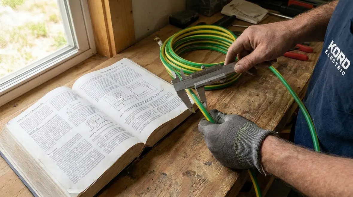
Section 250.166 provides the method to size the DC grounding electrode conductor. While the section references the broader grounding and bonding chapter logic, it places emphasis on DC grounded electrode conductor sizing based on the rules in 250.66 and related provisions. In plain terms, the code tells us how to pick the conductor rating so it can handle the fault and transient conditions expected for the DC grounded system.
To make this practical, our expert service staff does not just recite the rule. We translate it into an approach your design reviewers can follow. First, we confirm the DC system grounding method used at your facility. Then we identify which electrode conductor is classified as the DC grounding electrode conductor in the setup. Finally, we apply the code sizing step and verify the conductor type and installation method will not undercut the design.
And yes, we have seen projects where the calculations were correct but the conductor selection or termination method was sloppy. That is like building a fire escape but forgetting to install the door. It still “looks” right from a distance, and then reality shows up.
If your facility teams are also trying to connect this sizing logic to broader safety expectations, it can be helpful to view it alongside targeted resources on scope and application, such as Kord Electric’s coverage of 2026 NEC application requirements and related NFPA 70 grounding and bonding guidance, so DC conductor choices stay aligned with the rest of the electrical protection chain.
How our technicians confirm DC GEC sizing before drawings leave the office
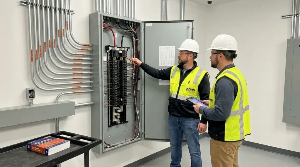
At Kord Electric, we follow a process built for commercial and industrial projects, where schedules are real and inspection scrutiny is even more real. Consequently, our technicians review both the technical assumptions and the physical installation plan. They do this because DC grounding electrode conductor sizing is not only about meeting a number. It also links to installation integrity, mechanical protection, and correct bonding behavior across the system.
Here is how we typically confirm NEC DC GEC sizing on active projects:
- We review the DC source and grounding arrangement so we correctly identify the conductor category used for the grounded electrode path.
- We verify conductor length and route to ensure the proposed installation aligns with code expectations for the grounding electrode conductor.
- We check terminations and bonding points because poor connections can create resistance, heat, and performance problems during fault conditions.
- We coordinate with the facility’s electrical one-line and equipment layout so the grounding path stays continuous and traceable for inspection.
- We document the reasoning so your stakeholders can see why the conductor size and method were chosen.
Meanwhile, when we explain this to site teams, we keep it calm and clear. Our people explain the “why,” not just the “what,” because that helps others maintain the design during changes, upgrades, and expansions.
For complex facilities where DC systems interact with large AC distribution, emergency power, or specialty equipment, our team often pairs this review with broader NEC evaluations, such as branch circuit scope and breaker application checks, so DC grounding remains consistent with upstream and downstream protection expectations.
Common mistakes we see in DC grounding electrode conductor sizing
Design teams do not fail on purpose. Yet mistakes happen, especially when a project blends multiple trades and multiple timelines. So we point out the issues we most often see in commercial and industrial facilities.
First, some teams apply AC grounding logic to DC systems without checking the DC specific conductor requirements. Even if the conductor size ends up similar, the reasoning can be wrong, and inspectors notice reasoning errors. Second, teams sometimes ignore the difference between bonding conductors and grounding electrode conductors. Third, we see projects where drawings show the correct conductor size but fail to detail the conductor type, routing, and termination quality required to support the design.
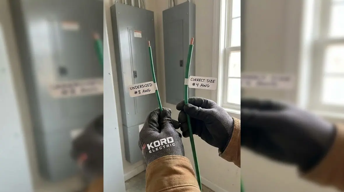
Next, the most expensive mistake is the one discovered after installation. When a conductor is undersized, the system can face higher impedance paths and stress protective device operation. When a conductor is installed incorrectly, it can also compromise long term performance. Therefore, we prefer to catch these issues during design review or pre install walkdowns.
Now for a little humor, because even codes deserve a laugh. People will spend weeks arguing about battery specs and inverter efficiency, and then they treat grounding like it is an afterthought. Grounding is not an afterthought. Grounding is the bouncer at the club. You can think you got in fine, but if the bouncer is missing, the whole place gets shut down.
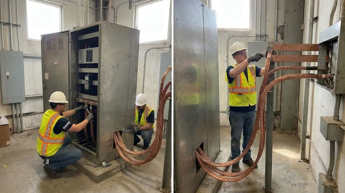
For facility leaders reviewing past projects, this is also a good moment to line up DC grounding designs with higher level NEC guidance from resources like Kord Fire’s NFPA 70: All About The National Electrical Code (NEC), so gaps in documentation or misapplied assumptions do not linger unnoticed.
Coordination with other NEC grounding rules and facility systems
When we build DC grounding plans, we do not treat NFPA 70 Section 250.166 as a standalone island. Instead, we coordinate it with surrounding rules that affect the full grounding and bonding strategy. This matters for large commercial and industrial buildings because the electrical system does not live in one compartment.
For instance, your facility may have equipment grounding conductors, bonding jumpers, service bonding, and special equipment requirements. Additionally, some installations also involve emergency power and life safety loads. As a result, the DC grounding electrode conductor must integrate into the larger grounding network without creating conflicts or unintended parallel paths.
We also coordinate with the facility’s broader compliance expectations. Kord Electric works with commercial and industrial property owners and builders who need dependable documentation for inspections, maintenance, and future modifications. So, we align the DC grounding electrode conductor design with the facility’s system architecture, labels, and maintenance planning.
If your teams are simultaneously reviewing topics like NEC scope, branch circuits, or breaker applications, weaving DC grounding discussions into those reviews helps keep the entire protection chain consistent instead of treating each decision like a separate island of code text.
Installation details that protect the sizing you calculated
Even when the calculation is correct, real world installation can still break the intent of code requirements. Therefore, we focus on installation details that protect the NEC DC GEC sizing decision.
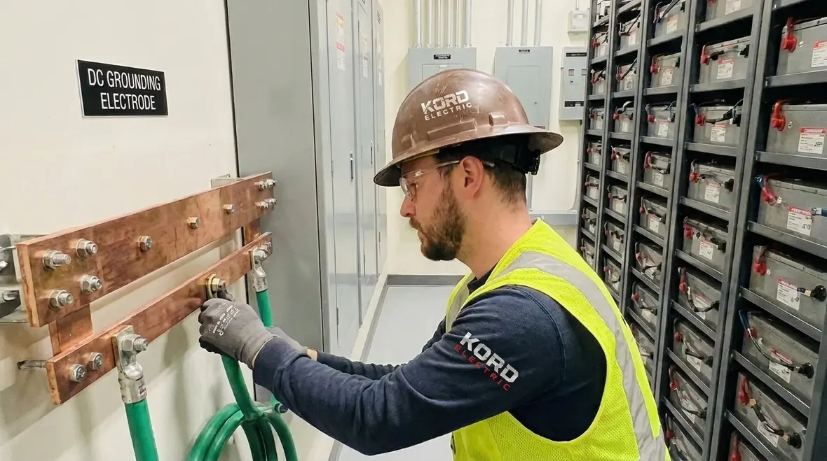
First, the conductor must maintain proper integrity along its route. That includes physical protection where damage risk exists, and correct support where required by the installation method. Second, terminations must be made with listed components and proper torque or attachment methods as applicable. Third, we check that the grounding electrode conductor connects to the correct electrode system elements, with consistent bonding practices.
Then we verify labeling and recordkeeping so the grounding path remains clear during maintenance. Many facilities add equipment over time, and a clear grounding record prevents guesswork later. Guesswork is how you end up with “mystery conductors” that no one can explain, and that is a comedy nobody requested.
For facilities in dense jurisdictions where inspections are frequent, we often recommend tying these installation checks into broader service plans like Los Angeles County electrical services, so DC grounding reviews happen alongside other maintenance and upgrade work instead of as a last-minute scramble.
Dual column quick-reference for field teams
Design focus for DC grounding electrode conductor
- Confirm the system grounding method
- Apply the sizing approach in Section 250.166
- Use correct conductor type and rating
- Match route and connection points to drawings
- Document assumptions for review
Field checks our team performs
- Inspect terminations and bonding points
- Verify conductor integrity along the route
- Check support and physical protection
- Confirm electrode connection details
- Ensure label and record alignment
Field teams can keep this quick reference close while using more detailed resources like Kord Electric’s National Electrical Code guides, so decisions in the vault, in the equipment room, and at the DC source all trace back to a consistent interpretation of NEC grounding and bonding expectations.
FAQ about NFPA 70 Section 250.166 and DC grounding
Conclusion and call to action
If your commercial or industrial project includes DC systems, do not treat DC grounding like paperwork luck. We help Kord Electric clients apply NFPA 70 Section 250.166 correctly, confirm NEC DC GEC sizing with clear documentation, and verify installation details that hold up under inspection. Our technicians and expert service staff explain the reasoning in plain language and support the work end to end. If you want a confident design and a calm jobsite, contact Kord Electric for a review today.
To keep your grounding decisions aligned with the rest of your electrical safety plan, you can also review companion articles on NFPA 70 structure, application scope, and equipment protection. Together, these resources give your team a practical map from codified rules to real, buildable DC grounding paths that protect people, equipment, and uptime.