NEC Feeder Diagram Requirements NFPA 70 Section 266.7
In commercial and industrial facilities, electricians do not “guess” when power needs to land exactly where it must. That is why NEC feeder diagrams requirements matter from day one. In NFPA 70 Section 266.7, feeder diagrams must show the path of conductors, identify the source, and clarify how circuits connect through switchboards, panels, and switchgear. At Kord Electric, we treat these diagrams like the blueprint for troubleshooting, not a decorative drawing to hang beside the coffee machine. Then our team of trained technicians and expert service staff explains the logic behind each requirement in plain language, so building owners and facility managers do not get stuck reading between the lines. And yes, we have seen diagrams that looked confident but said nothing useful. That is how you end up paying for “mystery maintenance,” and nobody likes that bill.
What NFPA 70 Section 266.7 demands for feeder diagrams
NFPA 70 Section 266.7 focuses on feeder diagrams that make the electrical system understandable and traceable. To meet the intent, feeder diagrams must communicate more than a single route. Instead, they must reflect the practical layout of the power system so that others can follow it safely during design, installation, and later maintenance. Therefore, the diagrams need to indicate key items that impact safe operation, such as the feeder origin, the connected equipment, and the conductor identification approach used in the field.

In other words, a good feeder diagram reduces confusion when something shifts, a breaker trips, or load changes after a renovation. Furthermore, it helps technicians confirm that the system matches the approved design. Our technicians at Kord Electric frequently find that when feeder diagrams are missing details, the team ends up doing extra field verification. That leads to delays, repeat visits, and the kind of time loss that makes project schedules feel like they are running through wet cement.
NEC feeder diagram requirements that keep maintenance predictable
Commercial and industrial electrical systems evolve. New tenants move in, equipment gets replaced, and controls get upgraded. As these changes happen, a feeder diagram should still guide safe work. For that reason, NEC feeder diagram requirements should support three daily realities: identify the correct feeder quickly, verify the correct connection during work, and restore service without guesswork.
From our experience, feeder diagram quality usually improves when teams treat documentation like a control system. They keep it current, they align it with labeling practices, and they link it to the actual equipment layout. Moreover, diagrams should not contradict field labels. When the drawing and the label disagree, technicians must spend time resolving the mismatch before they can even begin the task.

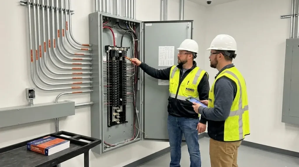
To keep things clear, we recommend that facility teams ask for diagrams that show the relevant hierarchy: source equipment to overcurrent devices to downstream panels and loads. Then we ask our technicians to review the drawing against the equipment nameplates and labeling scheme. That review catches issues early, before the first power event tests the system’s patience.
How feeder diagrams tie into labeling, conductor IDs, and short-circuit planning
Feeder diagrams do not live alone. They connect to labeling systems and conductor identification in the real world. Consequently, when a diagram uses conductor designations that match the installed conductors, technicians can trace the circuit without pulling random covers. That reduces risk and it reduces downtime. Additionally, accurate feeder diagrams support coordination efforts, including overcurrent protection selection and planning for abnormal conditions.
At Kord Electric, our expert service staff explains this relationship in meetings that do not make people yawn. We outline how the feeder diagram supports the entire chain of work, from initial power distribution to later troubleshooting. Then we show how the diagram should support the conductor numbering scheme used throughout the building.
Here is the practical takeaway. When conductors have consistent IDs, and when the diagram reflects those IDs, technicians can confirm the correct feeder and isolate the correct section. That matters especially in major property buildings where downtime costs money fast. If a facility manager thinks “we will figure it out later,” we politely remind them that later often arrives with alarms, and alarms are not known for patience.
Document quality matters more than the paper
Some teams treat feeder diagrams like a compliance checkbox. However, in a real commercial and industrial environment, documentation becomes a tool. Therefore, diagram quality matters. Quality includes clarity, completeness, and a layout that technicians can use under time pressure.
For example, a diagram that uses vague symbols or unexplained notes forces the field team into extra interpretation. That interpretation takes time and it increases the chance of mistakes. Meanwhile, a diagram that maps each feeder to its equipment with clear identifiers supports quick, safe decisions. In addition, a diagram that reflects changes after renovations prevents “documentation drift,” where the building reality moves ahead of the drawings.
To avoid drift, we encourage building owners to plan for updates as part of every electrical change. Kord Electric helps teams maintain diagram sets so that service staff can rely on them. And yes, we sometimes joke that a stale diagram is like a calendar invite that still says the meeting happened last month. Everyone looks confused, and the person who built it always insists it is “probably still right.”
Best practices for keeping drawings current after upgrades
Commercial and industrial upgrades happen constantly. New mechanical equipment adds load. Lighting retrofits change control panels. Electrical rooms get reconfigured. As a result, the feeder diagrams must update to match the as built conditions. Otherwise, teams inherit a future problem they never created, and that is a classic case of “blame without facts.”
When we work with facility managers, our approach is straightforward. First, we confirm what changed in the field. Next, we update the feeder diagram to reflect new feeders, removed feeders, and any reassignments of connections. Then we align conductor IDs and device labeling with the updated drawing. Finally, we make sure the documentation set stays in the place where service staff can find it quickly, even during a late shift when everyone wants the problem to stop and the lights to turn back on.
Our team also explains a simple rule. If the electrical work changes how power leaves a source, the diagram must show it. This keeps technicians consistent across inspections, service calls, and future expansions. For more background on the NEC approach to understanding the National Electrical Code, many teams rely on educational resources like those published by Kord Electric and Kord Fire, including summaries that support ongoing compliance planning, such as Understanding NFPA 70, the National Electrical Code Explained for 2026 and the Kord Fire guide NFPA 70: All About the National Electrical Code (NEC) 2026.
How our technicians use feeder diagrams in the field
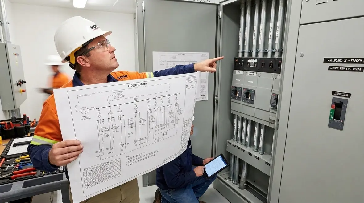
At Kord Electric, we do not treat documentation as a separate job that lives only in the office. We integrate it into how technicians work. Before troubleshooting, our technicians use feeder diagrams to map the likely path of power and to focus where the fault could land. Then they compare the diagram data to labels on the equipment. If something does not match, they resolve the discrepancy instead of forcing the assumption.
Because Kord Electric targets commercial and industrial facilities and major property buildings, we plan for systems where complexity is normal. When service staff handles multiple tenants or multiple floors, clarity becomes a safety factor and a cost control. Therefore, feeder diagrams help teams avoid opening the wrong sections and they help them communicate with building stakeholders in plain terms.
Additionally, our expert service staff explains findings in a way that supports decision making. They do not just say “it is fixed.” They explain what they found, what the diagram indicates, and what the next maintenance step should be. That approach keeps facilities operating with less uncertainty, and it reduces the number of repeat visits that cost both time and money.
Dual column snapshot: common gaps we see in feeder diagrams
| Diagram gap | Impact during service |
|---|---|
Feeder origin not clearly identified |
Technicians spend extra time confirming source equipment before isolating. |
Conductor IDs do not match field labeling |
More verification steps, increased risk of pulling the wrong cable. |
Outdated connections after tenant improvements |
Documentation drift leads to delays and longer troubleshooting windows. |
Missing notes that explain symbols or changes |
Misinterpretation under pressure, especially during after hours calls. |
FAQ about NFPA 70 and feeder diagrams
Conclusion: get feeder diagrams that your service staff can trust
Feeder diagrams are not just paperwork. When NFPA 70 Section 266.7 style information is clear and current, we help commercial and industrial facilities reduce downtime and improve safety. At Kord Electric, our technicians and expert service staff bring a practical approach: we align diagrams with real equipment, we update documentation after upgrades, and we make sure your team can trace feeders without guesswork.
If your facility is planning improvements or you suspect documentation drift, contact us now and let us help you tighten the system before the next alarm makes the decision for you. For facilities in Southern California, our Los Angeles County electrical services team supports everything from NEC feeder diagrams requirements verification to upgrades, testing, and ongoing maintenance.
Our technicians also coordinate with broader electrical and code compliance support, drawing on resources like our National Electrical Code explainers and design guides. Whether you are mapping new feeders, refining selective coordination, or planning for future capacity, we help you build documentation that matches the system you actually operate, not the one that only exists on an outdated print.