NEC Installation Limitations Explained for NFPA 70 300.4
At Kord Electric, we help commercial and industrial facilities follow the rules that keep power safe, stable, and predictable. Early on, we explain the NEC installation limitations tied to NFPA 70 Section 300.4 because this is where many projects drift off course. In the simplest terms, this section limits what installers can do when they route and support conductors. However, the NEC does not “ban creativity”; it channels it. And yes, we see the same mistakes more often than a sitcom repeats a punchline.
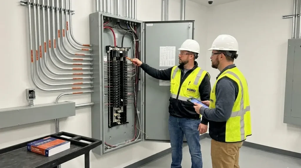
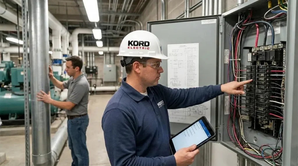
To keep projects clean and inspections smooth, our technicians and expert service staff walk building teams through the NEC install boundaries, so the plan in the office matches the reality in the field. Then, we document the approach in a way inspectors can follow without making anyone sweat through a hard hat.
What NFPA 70 Section 300.4 requires for conductor runs
NFPA 70 Section 300.4 focuses on installation limitations for conductors, especially where building conditions change. In practice, we treat it as a “no shortcuts” rule. First, we look at how the conductors leave equipment, then how they move through spaces, and finally how they get secured and protected. Next, we compare that plan to the NEC language that governs these situations. When a design team assumes a generic routing will pass, our technicians slow the process down and verify the constraints.

Our approach stays straightforward. We do not guess, and we do not rely on “it usually works.” Instead, we confirm what the wiring method allows, what the building environment demands, and what the installation method requires. As a result, the facility gets a power system that behaves as intended during normal operation and during fault conditions.
Why NEC installation limitations explained matter in commercial and industrial work
Commercial and industrial facilities live under higher loads, tighter timelines, and more scrutiny. Therefore, NEC installation limitations explained is not academic. It becomes a practical checklist that prevents rework, delays, and the expensive kind of “oops.” When a conductor route ignores the NEC boundaries, the system may still power up, but it can fail later. Worse, it can complicate future expansions when other trades need access and the original installation blocks them.
We often see confusion around how routing limitations connect to grounding, support, and protection. Additionally, changes in ceiling voids, cable trays, service corridors, and plant areas can shift what is acceptable. Our expert service staff explains these connections in plain language so that building owners, engineers, and contractors speak the same technical dialect. If the project team cannot repeat the rules back correctly, we pause and clarify.
For teams that want a broader code context alongside NEC installation limitations explained, Kord Electric’s resource Understanding NFPA 70: The National Electrical Code Explained for 2026 helps connect high-level NEC direction to day-to-day installation choices and inspection expectations in commercial and industrial buildings.
How we apply routing limits to tray, conduit, and cable support
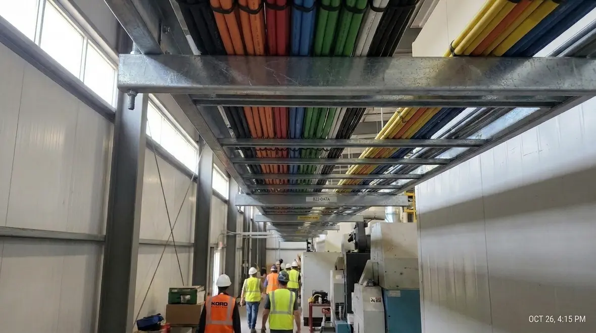
In real buildings, conductor paths rarely look like straight lines. However, the NEC expects the installation to stay within clear limits. For that reason, we inspect the full path: from switchgear and panels to branch circuits, then into device locations. After that, we focus on support and protection because the conductor method affects what is allowed.
Our technicians typically handle three practical areas:
- Routing changes: We verify bends, offsets, and transitions match the wiring method rules.
- Securing and support: We ensure the supports keep conductors properly positioned and protected against strain.
- Protection from damage: We confirm the installation uses the right protection where mechanical or environmental risks exist.
Then, we coordinate with the site plan. For example, cable tray spacing, separation needs, and access clearances influence how conductors can enter equipment rooms and utility corridors. Consequently, even a well designed single run can fail compliance if the installer takes a shortcut at a transition point.
We also make sure the as built drawings match the installed reality. In other words, we avoid the classic “the drawing says yes, the field says maybe” problem. Inspectors do not grade based on hope. They grade based on what exists.
Common failure points we see during field verification
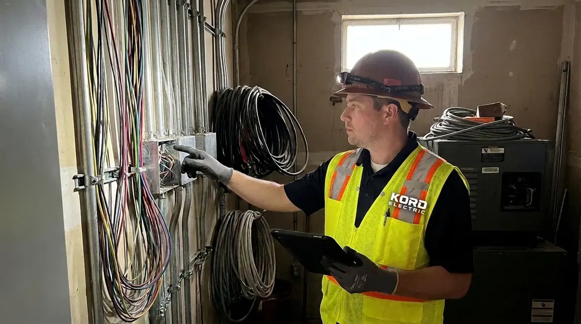
Even strong teams can trip on NFPA 70 requirements when schedules squeeze them. Therefore, we run field checks that look for patterns. When we spot a trend, we correct it early. That reduces change orders and keeps the facility on track.
Here are common failure points we verify during commissioning and pre inspection:
- Improper transitions: Conductors moving between different wiring methods without meeting the constraints.
- Unsupported sections: Runs that look fine at first glance, yet lack the support needed for the method.
- Protection gaps: Areas where the route passes through zones that can cause wear, impact, or heat stress.
- Unclear routing intent: When drawings show a path but do not define how the installer handles routing around obstacles.
To keep this from becoming a blame game, we explain the “why” behind each correction. Then, we show teams how to document it so the next phase of work does not reintroduce the same issue. In short, we build compliance into the workflow, not just into the final inspection packet.

Coordination with fire and life safety systems in major property buildings
Large facilities rarely have only one electrical story. Power systems interact with fire alarm circuits, emergency equipment, and life safety controls. While NFPA 70 addresses electrical installation requirements, coordination still matters because the building must function as an integrated system.
That is why, when we support projects, we coordinate with the life safety scope early. We pay attention to separation practices and to how wiring methods route around hazards. Additionally, we make sure the installation details do not create access conflicts that slow down emergency system testing. If the team cannot reach devices for maintenance, then “compliant on paper” turns into a maintenance headache.
We also reference the broader code landscape that property teams follow, including NEC related guidance often discussed in fire and electrical code training resources. When building owners and managers seek guidance, they usually want a clear path, not vague reassurance. Therefore, we keep our explanations grounded in field reality.
For teams who want a wider context on national electrical code concepts and how those rules connect to fire protection conversations, resources such as Kord Fire and Kord Fire Australia often help set the foundation. And for property teams that deal with water based fire protection planning, fire pump guidance from organizations like firepumps.org helps align life safety design decisions with system operation.
Step by step, how Kord Electric documents compliance
Compliance does not live in someone’s memory. It lives in documents. Therefore, we use a method that balances technical care with jobsite clarity. First, we review the electrical design intent. Next, we map it to the actual route and mounting plan in the building. Then, we collect proof that supports the NEC installation limitations requirements across the project.
Our documentation typically includes:
- Route and method notes that show how conductors move through each area.
- Support and protection verification that confirms the installation matches the wiring method.
- Redline tracking that captures changes before work closes out.
- Closeout packets that help facilities maintain and expand without guesswork.
When our technicians explain these steps, we keep the language simple and practical. We want a facility manager to understand what was done and why. We also want an inspector to see a complete story, not a collection of loose facts. After all, nobody wants to spend inspection day decoding a “mystery run.” That is not teamwork. That is a scavenger hunt, and we are done with those.
Because many of these documentation practices tie directly into what inspectors expect to see, our NEC installation limitations explained approach often pairs naturally with code-focused services Kord Electric provides for commercial properties. In regions with detailed requirements for Los Angeles County electrical services, this level of planning and record keeping helps projects move through permitting, field inspections, and future upgrades with fewer surprises.
NEC installation limitations explained FAQ
Professional next steps for your facility
If your project involves conductor routing, cable trays, conduit paths, or equipment transitions, Kord Electric can help you keep it compliant and maintainable. Our technicians and expert service staff explain NEC installation limitations in plain terms, then verify the field work matches the plan. If you are planning an install, commissioning a retrofit, or preparing for inspection, contact us now. We will review the approach, flag risks early, and help your team move forward with confidence.
And if your facility is preparing for broader electrical modernization work, pairing this NEC installation limitations explained focus with long-range planning resources on the Kord Electric blog can help you align conductor routing decisions with future upgrades, life safety coordination, and evolving NFPA 70 guidance.