NFPA 70 250.144 NEC Multiple Circuit EGC Connections
Kord Electric focuses on one thing: keeping commercial and industrial electrical systems safe, code compliant, and ready for real life. When multiple circuits share an equipment grounding conductor, NEC multiple circuit EGC connections matter, especially under NFPA 70 Section 250.144. In plain terms, that rule helps others understand how the grounding path stays solid when equipment serves more than one circuit. And while that sounds simple, electrical work rarely behaves like a sitcom script. It acts more like a long season where every episode adds a twist.
In this article, a writer with our team mindset explains what Section 250.144 requires, why it exists, and how we handle it for major property buildings and industrial facilities. You will also hear how our technicians and expert service staff walk people through the “why” behind the details, because code knowledge should not feel like homework.
What NFPA 70 250.144 really controls for grounding
NFPA 70 Section 250.144 addresses how equipment grounding conductors, often called EGCs, connect when multiple circuits terminate at the same equipment. First, it sets boundaries so the protective grounding path does not get split, delayed, or made unreliable. Next, it requires that when conductors belong to more than one circuit and connect to the same box, equipment, or enclosure, the bonding and grounding method supports safe fault clearing.
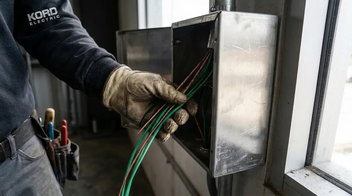
Now, grounding rules can feel like they exist to frustrate humans, but they actually exist to save lives and protect property. When a fault occurs, you want enough current to trip the overcurrent device fast, while keeping exposed conductive parts at a safe potential. Therefore, the EGC connection rules aim to keep the impedance low and the path dependable.
Our expert service staff often says this during site visits: “Your grounding system is not a suggestion. It is the seatbelt.” And yes, the seatbelt does not get noticed until the day you need it. Then suddenly everyone understands why it matters.
When multiple circuits land on the same equipment, what changes
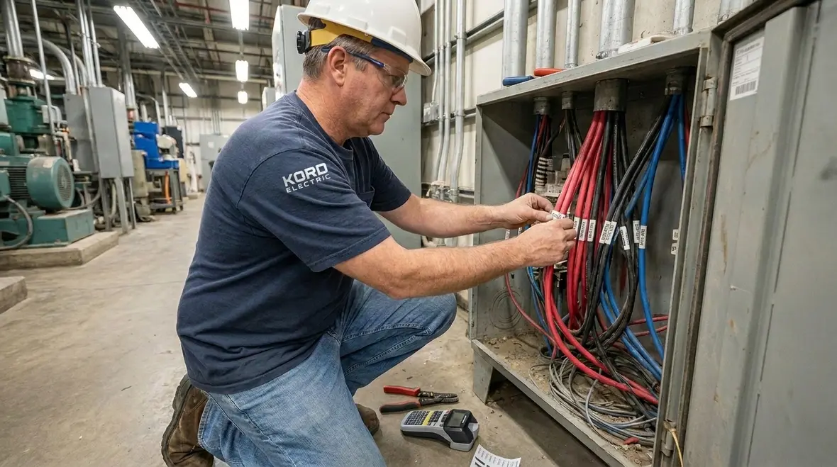
On commercial and industrial jobs, it is common to find scenarios where the same piece of equipment gets fed from more than one circuit. For example, that equipment can include large panels, distribution gear, HVAC electrical gear, motor controllers, switchboards, or other major building systems that serve multiple loads. When that happens, the installation must still provide a correct and continuous equipment grounding conductor path for each circuit.
What changes is how we handle the connections. Instead of treating each circuit grounding termination like a solo act, we design the connections so the EGCs work together as one safe system. Also, the bonding and terminations must follow the NEC approach so they allow fault current to return through the intended grounding path.
However, this is where mistakes show up in the real world. Someone may combine conductors in a way that looks neat, but does not meet the rule. Or they may connect one grounding conductor while another is handled differently. To be clear, “it seems grounded” is not the standard. The installation needs to follow the NEC requirements for NEC multiple circuit EGC connections and the intent behind Section 250.144.
Designing grounding for equipment that serves more than one circuit
For equipment that serves multiple circuits, our team treats the enclosure like a shared platform, not a free-for-all. Each circuit needs a clearly defined equipment grounding conductor connection that ties into the overall bonding and grounding strategy. That includes verifying that grounding bars, bonding jumpers, and terminations are rated and listed for the combination of conductors they will serve.
Instead of relying on “there is a green wire somewhere,” we map out where each NEC multiple circuit EGC connection begins, where it terminates, and how it stays continuous through pull boxes, raceways, and enclosures. This is also where documentation, labels, and as-built drawings pay off when someone returns years later to add a new circuit or troubleshoot an issue.
How we apply NEC multiple circuit EGC connections in the field
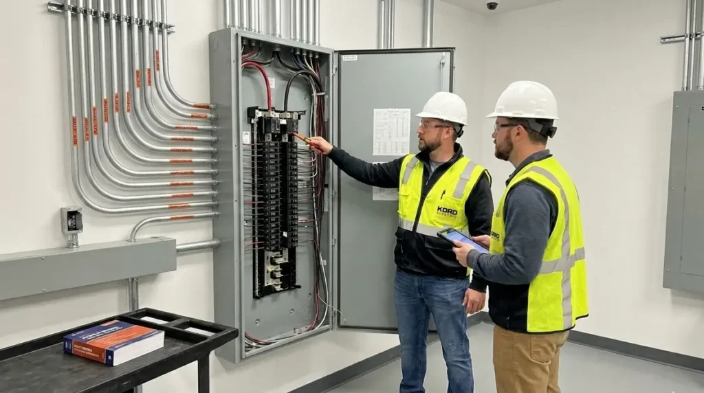
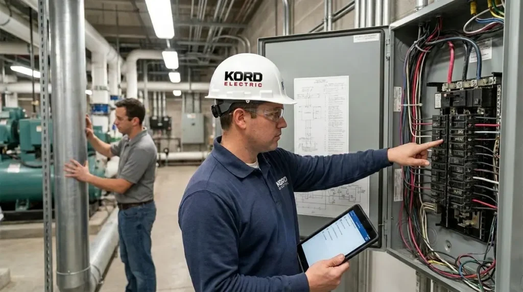
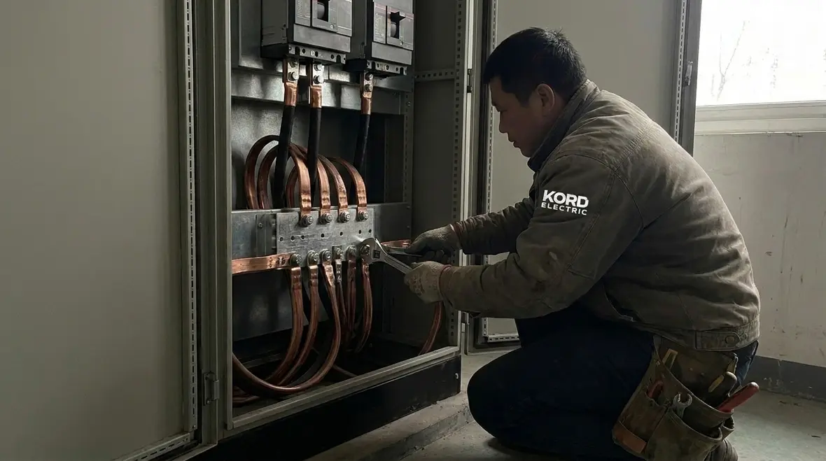
Our technicians approach this section like they approach commissioning and testing. They slow down, verify details, and document what they see. First, we identify the equipment that receives multiple circuits. Then, we confirm where each feeder and branch circuit terminates and where the EGC must land. After that, we check that our bonding methods and grounding terminations match the rule and do not create loose or unreliable connections.
Because commercial and industrial facilities carry real operational risk, we also plan for maintenance. In other words, we avoid designs that lock crews into a corner during future service. We also keep workmanship clean so future troubleshooting does not turn into a scavenger hunt.
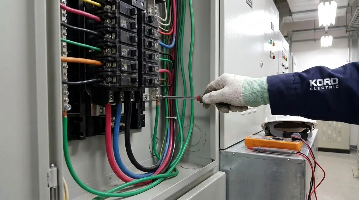
Next, we review how the conductors connect at the enclosure or equipment. We verify that each circuit grounding conductor receives proper termination and that the equipment grounding conductors maintain the correct continuity. If the job uses lugs, bonding straps, or bus systems, our team checks that they follow the intended grounding scheme. Then we make sure the connections will not loosen under vibration, heat, or regular building operations.
And yes, we sometimes see the “one wire to rule them all” method attempted by people who probably watched too much fantasy TV and not enough code training. Code grounding does not run on vibes. It runs on safe, repeatable connections that meet the standard.
Field verification steps that keep grounding honest
In the field, we follow a repeatable checklist so NEC multiple circuit EGC connections do not get overlooked during a busy day. That means confirming conductor sizes against the overcurrent device, checking torque on lugs, verifying listed terminals when multiple conductors are landed together, and tracing continuity so that no “mystery jumpers” become part of the fault path.
We also review how work from previous projects interacts with new circuits. If earlier installations left partial grounding bars, abandoned conductors, or unmarked terminations, our technicians clean that up and re-establish a clear, continuous path. That way, the next project does not inherit someone else’s guesswork.
Common installation problems we prevent before they become emergencies
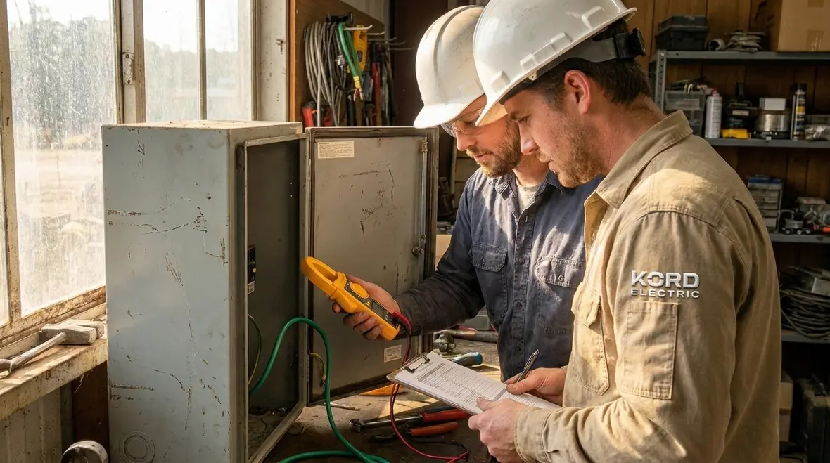
Experienced crews know that problems often start with assumptions. For this topic, the assumptions can include incorrect conductor grouping, confusion about bonding, and failure to keep the grounding path continuous. We address these issues through field checks, circuit tracing, and termination verification.
One frequent problem involves mixing up grounding and bonding responsibilities. Grounding focuses on the equipment grounding conductor path back to the system. Bonding focuses on connecting conductive parts so they share the same electrical potential. When those roles get blurred, protective devices may not trip as expected, and that is not a small risk.
Another problem involves terminations. If a termination uses the wrong lug size, the wrong conductor arrangement, or an insufficient connection method, then resistance can rise. As resistance rises, heat rises too, and that can damage equipment and create a hazard.
Also, some sites neglect the “multiple circuits” aspect during design review. They might prepare drawings that treat circuits like separate islands. Then the installer combines them at the equipment without the required NEC multiple circuit EGC connections approach. At that point, our technicians must correct the grounding scheme to meet Section 250.144 intent.
Finally, documentation gaps cause future confusion. When future work happens, crews need to know what the original grounding layout intended. That means we keep service notes and clarify the grounding method so the next technician does not have to guess. Guessing is fine for trivia night. It is not fine for grounding.
Real-world examples of issues we catch early
On real projects, we have seen panels where multiple circuits share an equipment grounding conductor that was never sized correctly for the largest overcurrent device. We have also found enclosures where neutral and ground bars were treated interchangeably, leaving a maze of connections that worked “for now” but would not hold up under fault conditions or inspection.
By catching these issues during maintenance visits or upgrade projects, we help building teams avoid emergency shutdowns, surprise inspection failures, and those late-night calls where everyone wonders why one tripped breaker took half a floor offline.
Why EGC rules matter for fault clearing and equipment protection
Electric faults do not ask for permission. They happen. When they happen in commercial and industrial environments, the goal is straightforward: provide a low impedance fault path so protective devices clear quickly. That reduces damage, limits arc flash risk, and protects both equipment and people.
Section 250.144 supports that goal by controlling how equipment grounding conductors connect when multiple circuits feed the same equipment. When the grounding path stays correct, the system can carry fault current along the intended route. Therefore, breakers and fuses operate in the expected way, rather than stalling or behaving unpredictably.
In practice, we connect this to real outcomes. When grounding is wrong, it can increase nuisance trips, cause hotspots, and lead to equipment failure. When grounding is right, systems run with fewer surprises and the facility maintains smoother operations.
Our expert service staff explains it in everyday language during walkthroughs. They point out that grounding is like a highway for fault current. If lanes get blocked or exit ramps get added, traffic does not move. In electrical terms, fault current does not clear fast enough.
Connecting grounding performance to business risk
From a facility perspective, NEC multiple circuit EGC connections are not just a technical detail. They directly affect uptime, equipment lifespan, and safety performance. A miswired or undersized grounding path can turn a simple fault into a major outage, damage gear that took months to source, or trigger an incident that draws the attention of insurers and regulators.
By treating Section 250.144 as part of a larger fault-clearing strategy, we help clients align protection devices, conductors, and grounding so that when something does go wrong, the system responds quickly and predictably instead of improvising under stress.
Coordination with other code needs on major property buildings
Section 250.144 does not exist alone. Commercial and industrial projects also involve other NEC parts related to grounding, bonding, wiring methods, overcurrent protection, and equipment enclosures. So while we focus on this specific rule, we also coordinate it with the broader electrical design.
For major property buildings, coordination affects everything from panel schedules to labeling to how crews access equipment later. Also, if the facility has multiple tenants or phased construction, maintaining the grounding scheme becomes even more important. We often assist with planning so future additions do not disturb the grounding method.
Additionally, we align our approach with the NEC guidance and widely used code references from trusted sources. For example, readers can review code breakdowns and NEC education materials such as the Kord Electric resource Understanding NFPA 70: The National Electrical Code Explained for 2026 to understand the larger picture, including how code concepts fit together across installations. Our aim stays consistent: help facilities build and maintain safe electrical systems that stand up to inspections.
And because we operate in different regions and project types, we also encourage clients to follow local adoption and amendments where applicable. Code text guides the work, but the local authority having jurisdiction sets the final expectations. We respect that process.
Planning grounding with future upgrades in mind
In growing facilities, today’s “final” panel is often tomorrow’s junction point for a new project. We help clients plan NEC multiple circuit EGC connections so they can scale without tearing out what was just installed. That means reserving capacity on grounding bars, coordinating conductor routing with mechanical and low-voltage trades, and documenting enough detail that a future designer can extend the system safely instead of guessing behind ceiling tiles.
This approach lines up naturally with the broader electrical infrastructure planning work we perform across commercial and industrial facilities, where coordination, clean documentation, and code-focused design keep projects from turning into last-minute heroics.
Featured FAQ for grounding and multiple circuit EGC connections
Note: After reading this, some people will want to jump straight into the paperwork. That is good. Others will want to jump straight into the panel. That is less good. Best practice is to plan the grounding approach first, then install and verify it thoroughly.
Conclusion and call to action
Kord Electric supports commercial and industrial facilities with practical, code focused electrical service. Our technicians and expert service staff apply NFPA 70 Section 250.144 grounding requirements so your NEC multiple circuit EGC connections remain safe, reliable, and ready for inspections. If your project includes shared equipment, multiple feeders, or phased upgrades, we help you plan the wiring, verify the terminations, and document the results. For facilities across the region, our Los Angeles County electrical services bring together code-conscious installation, disciplined maintenance, and responsive support so operations can focus on production, not power problems.
If you are preparing for upgrades, planning new equipment, or simply wondering whether your current grounding setup still matches the latest expectations, our team is ready to help. We review existing conditions, identify risks, and turn dense code language into a clear, buildable plan you can act on without guesswork or drama.
Reach out to us today for an evaluation and a clear path forward that keeps your facility protected, not surprised.