NFPA 70 315.45 NEC MV Joint Shielding Requirements Explained
NFPA 70 and NEC MV Joint Shielding: What Section 315.45 Really Demands
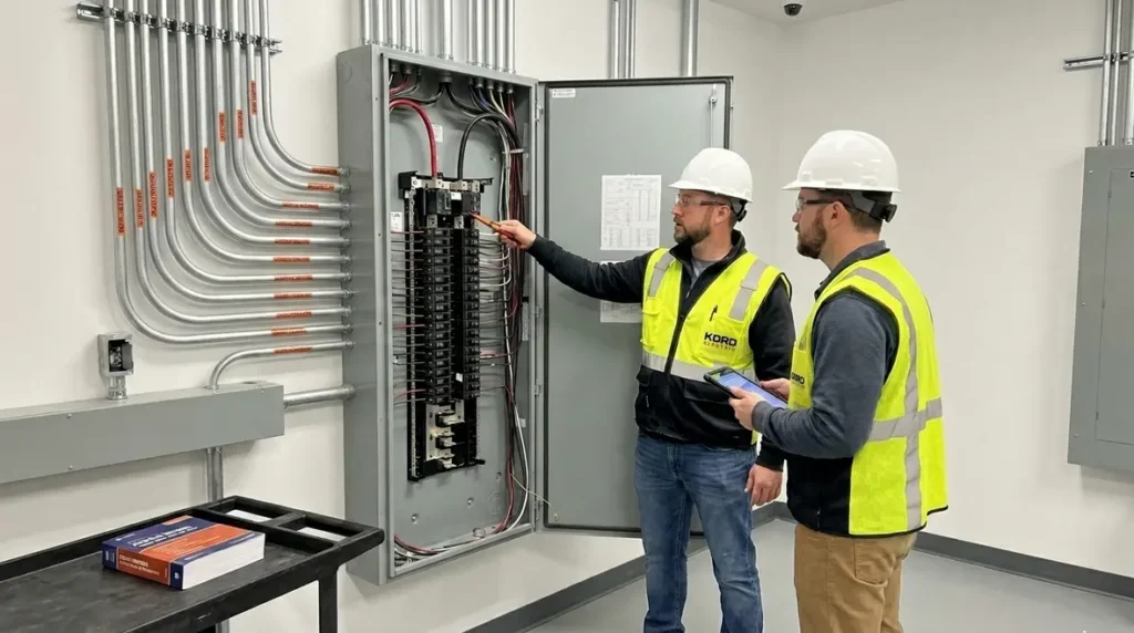
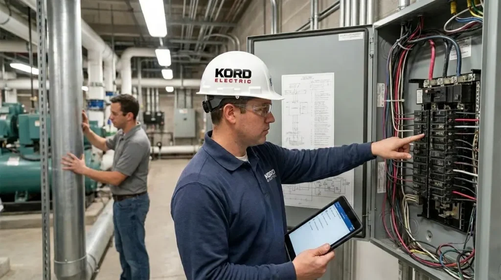
At Kord Electric, we help commercial and industrial facilities manage medium voltage power with confidence, not guesswork. In the first step of that effort, we focus on NEC MV joint shielding at medium voltage joints and terminations, because NFPA 70 Section 315.45 makes those protection details hard to ignore. It does not ask for “nice to have” practices. Instead, it pushes for a system that controls electrical stress, limits corrosion paths, and protects the integrity of the connection zone. And yes, we have seen what happens when someone treats a joint like it is just a place to “plug things in.” The power grid does not care about intentions, only outcomes.
In this article, we explain how Section 315.45 works, how our expert service staff walks sites through compliance, and what practical steps reduce risk for major property buildings and multi-tenant operations.
How 315.45 Fits the Bigger Picture of MV Systems
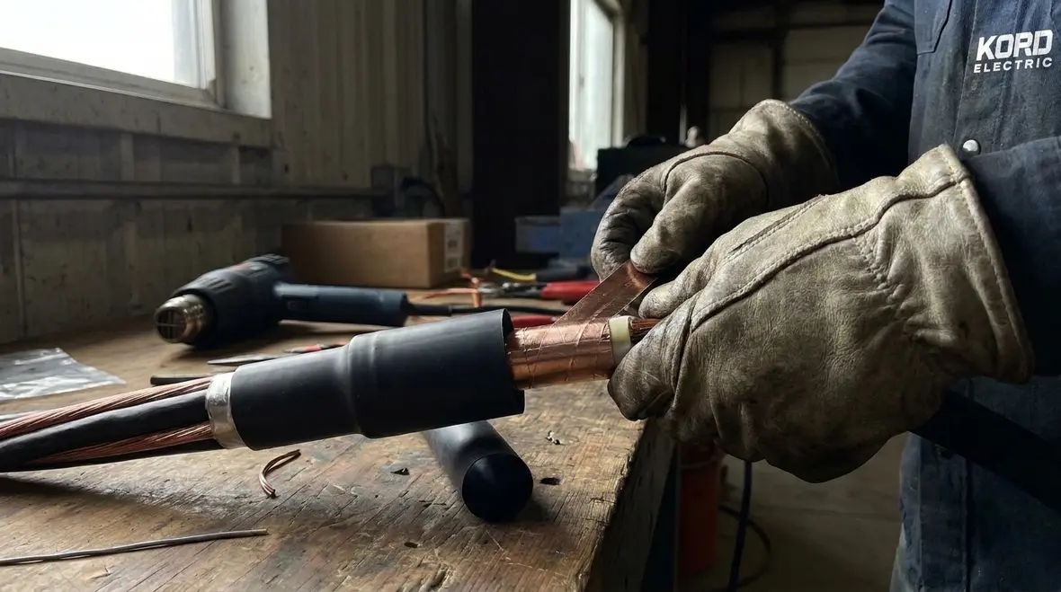
When teams build or maintain medium voltage circuits, they often focus on switchgear, cables, and protection relays. However, field joints and terminations sit in a different kind of spotlight. They experience mechanical stress from installation, thermal cycling, and moisture exposure over time. Consequently, NFPA 70 Section 315.45 focuses on shielding at MV joints and terminations to keep those weak spots from becoming long term trouble.
Others sometimes assume shielding only matters for high noise environments or special industrial layouts. Yet in real facilities, the risk shows up as partial discharge, premature insulation aging, and unexpected tracking at interfaces. Therefore, the code intent centers on maintaining the electrical performance of the entire insulation system, not just the cable body.
Our technicians explain it in plain terms during on site discussions. First, they point out the joint is where the geometry changes. Next, they explain that electrical fields do not magically respect our schedules. Then they tie it back to shielding, so the connection behaves like the cable, rather than acting like a new electrical element.
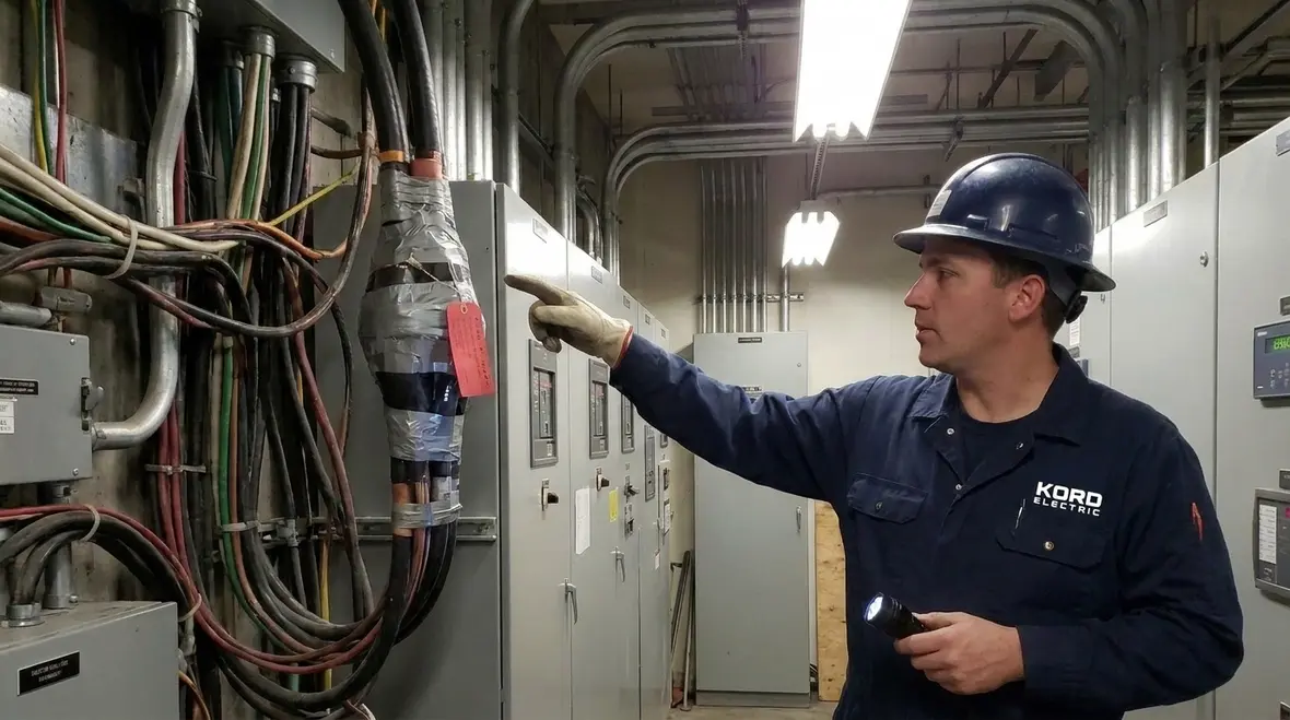
What “Shielding at MV Joints and Terminations” Means in Practice
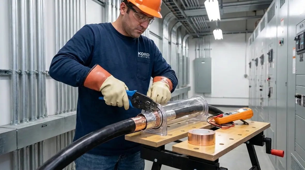
NFPA 70 Section 315.45 addresses how the shielding system continues through the joint and termination area. In other words, the shield does not end at a random boundary, because that boundary creates an unbalanced electric field. Instead, a complete and continuous approach helps control stress and reduces the chance of surface degradation.
In most commercial and industrial environments, the “practice” includes steps like ensuring proper conductive paths, using compatible materials, and installing the shielding system so it matches the electrical design of the cable. Additionally, teams should avoid improvising with mismatched parts. If the system expects a particular type of shield interface and the install uses a different approach, the result can look fine at first and fail later. That is the part that always feels like a plot twist, like a superhero reveal, but with worse consequences.
Our expert service staff also reminds clients that MV joint work often involves multiple trades. Therefore, coordination matters. We help facilities keep the process consistent, especially when production schedules try to steamroll quality.
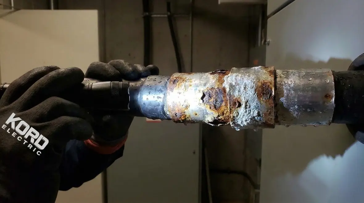
Common Failure Points We See on Major Property Buildings
Even when a site follows a written procedure, real conditions introduce risk. Over time, we see recurring issues that connect directly to shielding quality and continuity. First, installers sometimes under prepare surfaces or skip steps that ensure the conductive and insulation layers seat correctly. Then, they may compress components too tightly or leave gaps where electrical stress concentrates.
Second, many problems come from moisture management. Water does not politely wait for maintenance windows. Instead, it finds routes around cable jackets, terminations, and any interface where sealing does not hold. Over time, corrosion changes conductivity and can shift how the shield system performs. Consequently, the electrical stress pattern changes, and the joint becomes a weak link.
Third, we sometimes see shielding continuity treated like a check box. However, proper continuity also requires correct bonding practices and compatibility with the overall grounding and bonding scheme. Therefore, the shield is only as effective as the connection and the field workmanship.
To keep things calm and clear, our technicians walk through these failure points in site meetings, then they map each risk to a practical fix. We keep the conversation focused on commercial and industrial facility realities, not theoretical textbook ideas.
Step by Step: How Our Team Supports NEC MV Joint Shielding Quality
Every facility runs on timelines, but quality cannot run on hope. We approach medium voltage joint and termination work with a method that respects both safety and code intent. And since nobody wants surprises during commissioning, we start with planning.
- Review the circuit design and equipment interfaces: We confirm cable type, termination method, and bonding scheme so the shielding system matches the intended electrical behavior.
- Verify materials compatibility: We ensure the components used for the joint and termination support the required shielding and insulation interfaces.
- Prepare surfaces and interfaces properly: Our technicians treat preparation as a real step, not a “we did it, trust us” moment.
- Install and secure the shielding system: We maintain the intended continuity and control of electrical stress through the joint area.
- Confirm workmanship through checks: We verify installation details and coordinate any required documentation for facility records.
- Support commissioning and maintenance readiness: We help facilities understand what to watch for during future inspections and troubleshooting.
Meanwhile, our teams communicate in a way facility managers appreciate. We explain what we do, why it matters, and how it protects the facility’s uptime. After all, in a major property building, the “real world” means tenants, elevators, critical loads, and business schedules that do not pause for electrical learning.
Where NFPA 70 and the NEC Interact With Facility Safety
Many people hear NFPA 70 and think it is only a document name. However, for our customers, it becomes a safety framework that impacts how MV systems get installed and maintained. When we discuss shielding at MV joints and terminations, we connect it to the broader NEC approach to installation quality, conductor protection, and effective grounding practices.
At Kord Electric, we also align our process with the practical guidance many clients request from trusted sources, including how the NEC is explained in industry education material. For teams who want a deeper walk through of code structure and direction, we often point them to our resource Understanding NFPA 70: The National Electrical Code Explained for 2026, then connect those concepts back to real MV joint work in their buildings.
We make sure teams understand the goal: control electrical stress, reduce the likelihood of insulation breakdown, and keep the system predictable over time.
Additionally, we maintain an eye on the facility’s risk profile. A hospital wing, a data center area, or a large retail complex with heavy mechanical loads demands dependable power. Therefore, our technicians focus on consistent workmanship that supports safe operation, not quick fixes that fail under thermal cycling.
And if you think this sounds like we are saying “do it right the first time,” you are correct. The grid already has enough problems without adding ones we can prevent.
Dual Column Best Practices for MV Joint and Termination Shielding
When facility managers ask how to turn code language into field behavior, we often summarize NEC MV joint shielding guidance into a short set of paired best practices and reasons. It keeps conversations grounded in practical outcomes, not theory.
| Best practice | Why it matters |
|---|---|
| Maintain shielding continuity through the joint area | Controls electric stress so the connection behaves like the designed cable system |
| Use compatible components and follow installation instructions | Prevents mismatched materials from creating weak insulation interfaces |
| Manage moisture with proper sealing and installation discipline | Reduces corrosion and surface tracking risks that worsen over time |
| Coordinate bonding with the overall grounding plan | Keeps the electrical reference stable, supporting predictable shield performance |
| Document workmanship for future inspections | Improves maintenance planning and speeds troubleshooting during outages |
In parallel with these practices, we also help facilities verify that NEC MV joint shielding choices align with broader project goals, such as uptime expectations, expansion plans, and local authority requirements. That way, the shield does more than satisfy a line in NFPA 70 Section 315.45; it supports the full life of the system.
On large commercial campuses and major property buildings, we often connect this conversation to future upgrade work, including medium voltage distribution changes, emergency power additions, or power quality improvements. If your facility team is also planning larger electrical projects across Los Angeles County, our Los Angeles County electrical services overview helps you see how MV shielding, distribution design, and critical power support fit together in one coordinated plan.
FAQ
Conclusion: Ready to Tighten MV Joint Protection?
When a medium voltage joint fails, the cost rarely stays in the electrical room. It spreads into downtime, emergency response, and business disruption. That is why Kord Electric treats NEC MV joint shielding and NFPA 70 Section 315.45 requirements as core protection work, not optional paperwork. Our technicians and expert service staff explain the process clearly, install with disciplined quality, and help major property buildings protect uptime. If you want a practical compliance plan for your next joint or termination project, or you are ready to align MV shielding with your broader NFPA 70 strategy, Kord Electric can help you put the details in order before the next outage writes the story for you.
For facility leaders who want to connect NEC MV joint shielding decisions with overall code understanding, we also recommend reviewing our educational content on how NFPA 70 shapes modern installations. Pairing that knowledge with disciplined field work turns MV joints from quiet vulnerabilities into predictable, well-documented parts of your electrical system.