NFPA 70 Section 215.11 Autotransformer Feeder Circuit Code
NFPA 70 Section 215.11 and why Kord Electric cares about NEC autotransformer feeder circuits code
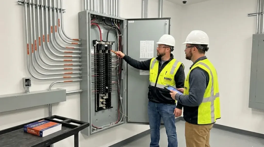
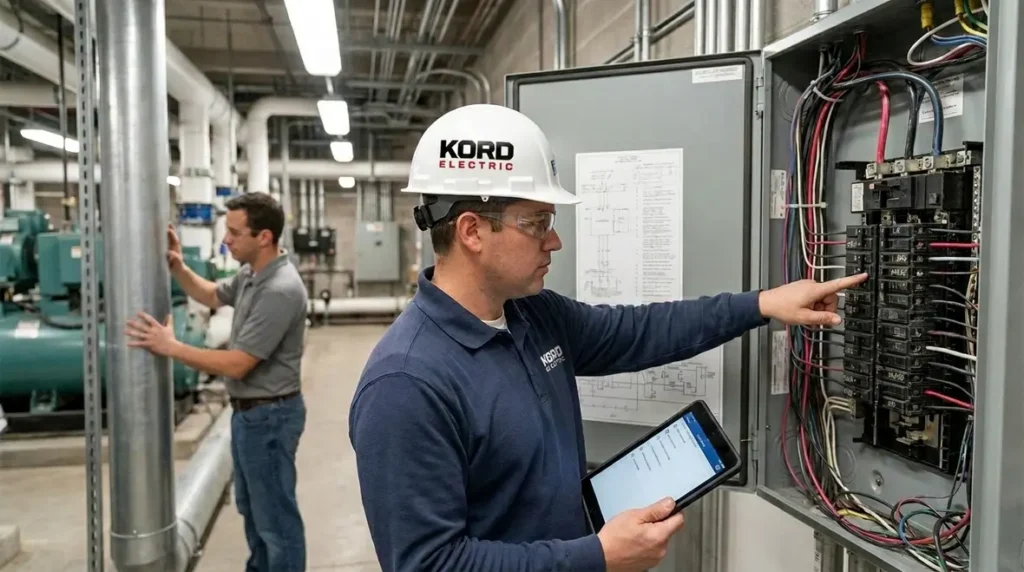
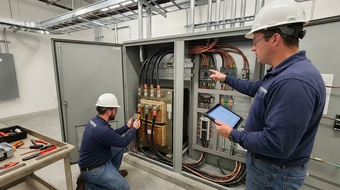
In commercial and industrial facilities, electricians do not get the luxury of “close enough.” We build, we test, and we document, because electrical systems decide whether businesses run or pause. That is why our technicians at Kord Electric take NFPA 70 Section 215.11 seriously and apply it to NEC autotransformer feeder circuits code planning for major property buildings. Early in the design, we look at how autotransformers shape the feeder circuit, then we align protection, conductor sizing, and connection rules so the system behaves the way the code expects when real-world conditions hit. And yes, we explain it in plain language too, because even if the code reads like a legal thriller, it does not have to be one for you.
Our expert service staff often says the same thing: if you treat this section like a checklist, it will bite you later. Instead, we treat it like a map. Then, we follow it step by step.
Where Section 215.11 fits in the NEC for autotransformer setups

NFPA 70 is not a single topic book, it is a system. Section 215 sits in the feeder and branch circuit territory, and Section 215.11 narrows the focus to feeder circuits that come from an autotransformer. That matters because autotransformers do not act like typical isolation transformers. Instead, they link circuits in a way that can change how fault current behaves and how the circuit needs to be protected.
Therefore, when others skip the intent of Section 215.11, they sometimes end up with mismatched protection and confusing voltage relationships. In addition, the wiring arrangement may look fine in the field, but the calculated behavior under fault conditions can be wrong. That is where our team helps on commercial and industrial projects and major property buildings. We review the design, then we verify the field plan fits the code rules, not just the equipment nameplate.
How autotransformer-derived feeders change protection expectations
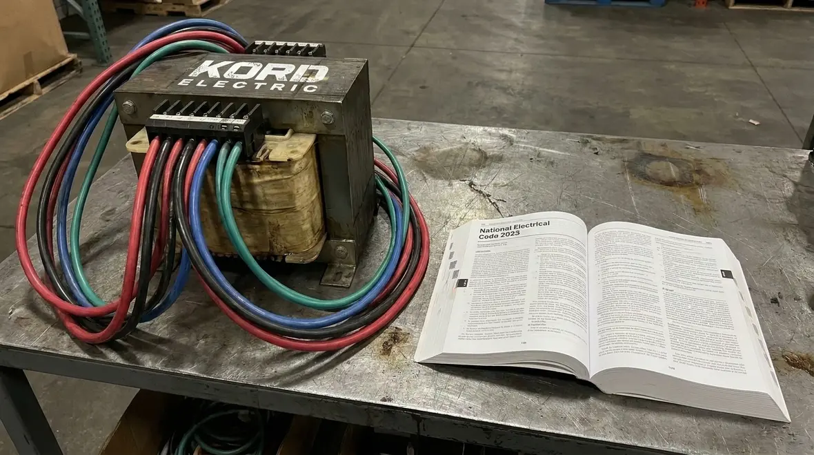
When an autotransformer creates the source for a feeder, the electrical system still needs to meet basic safety goals. However, the details shift. First, we evaluate what the feeder “sees” from a fault and overload standpoint. Next, we match that to the correct protective device requirements for the circuit. Then we confirm the conductor insulation and rating support the full duty cycle the facility will experience.
In practice, our technicians often explain it this way: a feeder circuit is not just wire. It is a story about current paths during normal operation, and it is also a story about what happens when something goes wrong. If the story has gaps, the protective devices may not clear faults at the expected times. And if that happens, the equipment and the building systems take the heat.
So, we keep the process methodical. We review the transformer connection method, we confirm how the feeder is derived, and we make sure the protective approach supports the code intent for NEC autotransformer-derived feeder circuits.

Conductor sizing and voltage assumptions under Section 215.11
Conductor sizing often feels boring to people, but it is like seatbelts. You notice them only when you need them. In autotransformer-derived circuits, we do not guess. We size conductors based on the correct design rules, and we apply the right voltage context for the feeder.
Also, many issues come from misunderstandings of voltage relationships. For example, some teams assume the feeder voltage behaves exactly like a straightforward secondary circuit. Meanwhile, the autotransformer arrangement can create a different set of conditions. As a result, insulation class, termination ratings, and equipment compatibility require careful attention.
That is why our expert service staff often works with designers and facility managers. We explain what to verify and what to document, so the installation matches the plan. We also help teams avoid late-stage rework, because revising cable sizes after installation is never as fun as people think. It is the electrical version of building a deck after the furniture arrives.
Design review: matching protective devices to real feeder behavior
After we confirm the feeder’s electrical context, we move to protection. Protective devices must handle overload, and they must interrupt faults safely. Yet, autotransformer-derived sources can complicate how fault current and operating conditions present themselves. Therefore, we analyze the system as a whole, not as isolated components.
At Kord Electric, we bring that thinking to commercial and industrial facilities. We do this because major property buildings often contain sensitive systems such as life safety loads, critical process equipment, and uptime driven production lines. So, we focus on continuity where it matters and safety where it counts.
Then we coordinate with the project team. We confirm settings, device types, and labeling needs. Moreover, we verify that the documentation supports maintenance staff during troubleshooting. A good electrical job should not require a detective with a magnifying glass just to understand the protection scheme.
Common field issues we help teams avoid
On-site, the problems are rarely from one dramatic mistake. They come from small mismatches: a conductor that does not meet the expected rating, a term that gets labeled wrong, or an installation detail that deviates from the design assumptions. Also, some teams struggle with the boundary between transformer logic and feeder logic, especially when multiple voltage systems share spaces.
Our technicians look for the patterns that repeatedly create trouble:
- Feeder labeling that does not match the derived voltage context
- Conductor termination practices that do not match the insulation and temperature expectations
- Protective device selection that does not align with the autotransformer-derived behavior
- Missing or incomplete documentation for maintenance teams
And sometimes, we catch the classic one: someone says, “It worked last time,” as if buildings run on habit. Buildings run on physics. Code guides that physics. Our expert service staff makes sure the system follows the rules, not the legend.
What Kord Electric does differently for major property buildings
We serve commercial and industrial facilities and major property buildings, and our process reflects that responsibility. First, we coordinate with design teams early, because most code compliance issues show up before the first panel is closed. Next, we verify key details during installation and testing, then we deliver documentation that facility teams can use.
Furthermore, we explain decisions clearly. Our communication style matters because electrical systems live in real buildings, with real people. Facility managers need calm, precise answers. Maintenance teams need straightforward labeling and traceable documentation. And project owners need confidence that the installation aligns with NFPA 70 and the NEC rules that govern feeder behavior from autotransformers.
If you want more context on how we interpret NEC requirements, you can explore resources through Kord Electric’s blog and related code discussions at Understanding NFPA 70, the National Electrical Code Explained for 2026 alongside additional NEC-focused articles on the Kord Electric blog. We also stay aligned with broader standards and safety perspectives through our partners at Kord Fire and Kord Fire Australia, plus additional industry references such as Fire Pumps. We do not treat these sources as substitutes for project engineering. Instead, we treat them as guidance while our team applies the rules to your specific facility.
FAQ on autotransformer-derived feeders and NEC requirements
Ready to align your autotransformer feeder plan with the NEC?
When a commercial or industrial facility depends on reliable power, we do not leave code compliance to chance. Kord Electric reviews your autotransformer-derived feeder circuit requirements under NFPA 70 Section 215.11, then we help your team install, document, and support the system with confidence. Our technicians and expert service staff explain the key decisions so your maintenance teams can act fast later. If you want a clear path forward for a major property building, you can also connect this work with broader electrical planning and maintenance by exploring our other NEC-focused articles, then bringing those insights into a project-specific design review.
For facility leaders planning broader upgrades, our Los Angeles County electrical services team can integrate NEC autotransformer feeder circuits code compliance into larger commercial electrical projects, from service upgrades to coordinated protection and maintenance planning.
When you are ready to turn NFPA 70 Section 215.11 from a line in the code book into a dependable, documented part of your electrical system, Kord Electric is ready to help.