NFPA 70 Section 310.1 Scope for NEC Conductor Sizing
In commercial and industrial electrical work, we never guess. We follow the NFPA 70 Section 310.1 scope, which sets the rules for sizing conductors used across many NEC applications. In this article, we explain the NEC conductor sizing scope in plain terms, then we show how our team at Kord Electric applies those rules on real projects. Our technicians and expert service staff take the time to walk owners and facilities managers through what matters, because the electrical system is not a “set it and forget it” situation. It is more like keeping a forklift running in winter. It works great until it does not, and then everyone remembers maintenance exists.
NFPA 70 Section 310.1 scope: how we size conductors the right way
In commercial and industrial electrical work, we never guess. We follow the NFPA 70 Section 310.1 scope, which sets the rules for sizing conductors used across many NEC applications. In this article, we explain the NEC conductor sizing scope in plain terms, then we show how our team at Kord Electric applies those rules on real projects. Our technicians and expert service staff take the time to walk owners and facilities managers through what matters, because the electrical system is not a “set it and forget it” situation. It is more like keeping a forklift running in winter. It works great until it does not, and then everyone remembers maintenance exists.
What Section 310.1 covers in the NEC conductor sizing scope
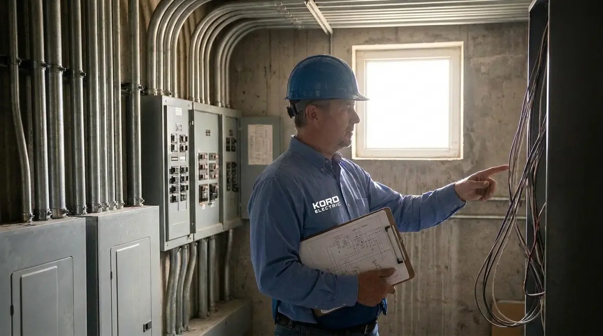
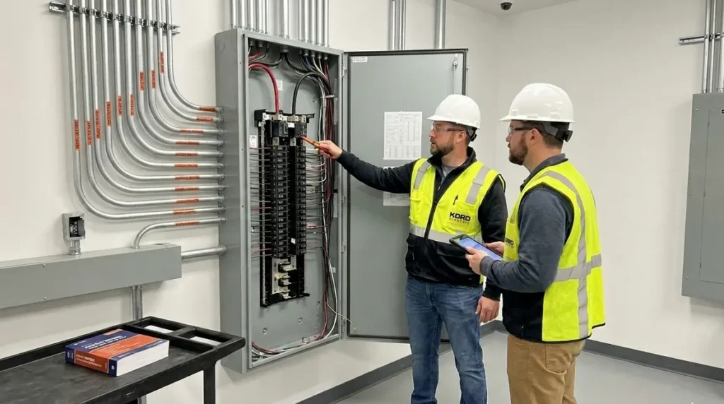
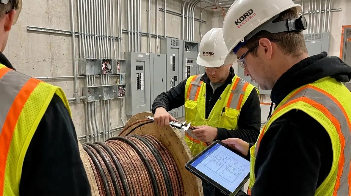
Section 310.1 establishes the basic scope for conductor sizing in the NEC. Therefore, it tells us which conductor sizing rules apply and under what general conditions. Next, it supports the rest of Article 310, where you find conductor types, insulation rules, and allowable ampacities in context. Put simply, Section 310.1 does not size every wire by itself. Instead, it sets the boundaries so the rest of the NEC can do the job.
When we support a major property building, we treat Section 310.1 like the map legend. If you ignore it, the map still exists, but you will walk into the wrong neighborhood. And in electrical design, the wrong neighborhood can become an expensive rework meeting.
Our expert service staff also explains that conductor sizing does not live in isolation. It connects to load calculations, temperature limits, wiring methods, and how the system operates over time. Then, it connects again when protection devices coordinate with those conductors. So, while Section 310.1 sets scope, the practical consequences show up later in troubleshooting, inspections, and long term reliability.
For teams who want a deeper code backdrop alongside Section 310.1, we often point them to our broader NEC overview in Understanding NFPA 70: The National Electrical Code Explained for 2026, where we connect conductor rules back to overall system safety and fire protection strategy.
How NEC conductor sizing scope connects to ampacity and temperature
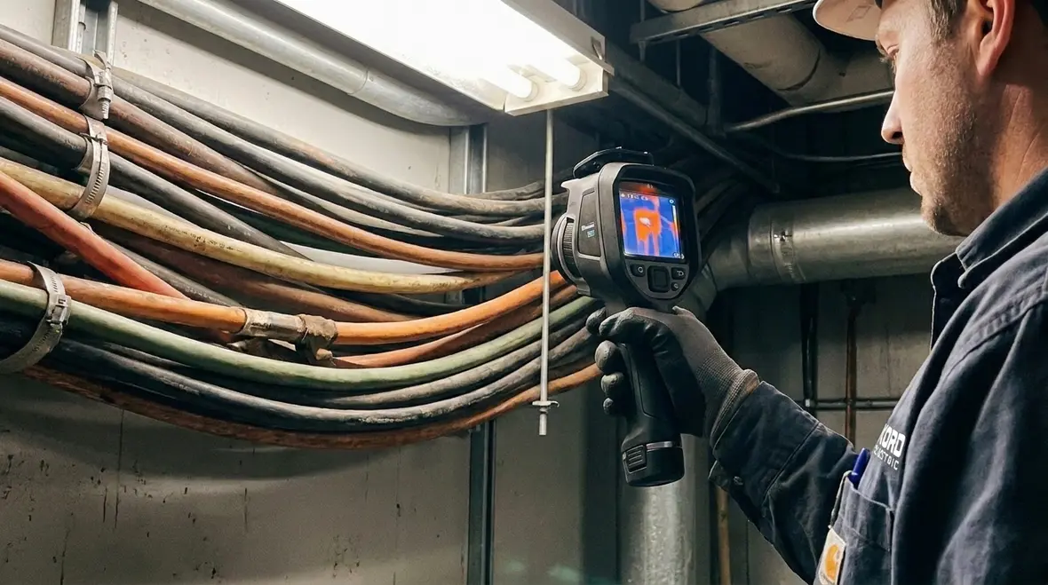
Once Section 310.1 sets the scope, we move to the heart of conductor sizing: ampacity. Ampacity depends on conductor properties, installation conditions, and thermal limits. For example, the same conductor can carry different current depending on insulation rating, number of current carrying conductors in a raceway, and how heat moves away from the wire.
Therefore, we do not treat conductor size as a single number. Instead, we look at how heat behaves where the conductor sits. And because commercial and industrial facilities often have long cable runs, dense mechanical rooms, and shared pathways, temperature effects matter more than people expect.
In our process, we also consider ambient temperature and any derating needs. Next, we align the conductor ampacity with the load and the required operating conditions. Our technicians explain the “why” step by step to facility decision makers, so they understand that wire size is not just compliance paperwork. It is safety, performance, and reduced risk of nuisance problems.
Installation conditions that change the calculation for sizing conductors
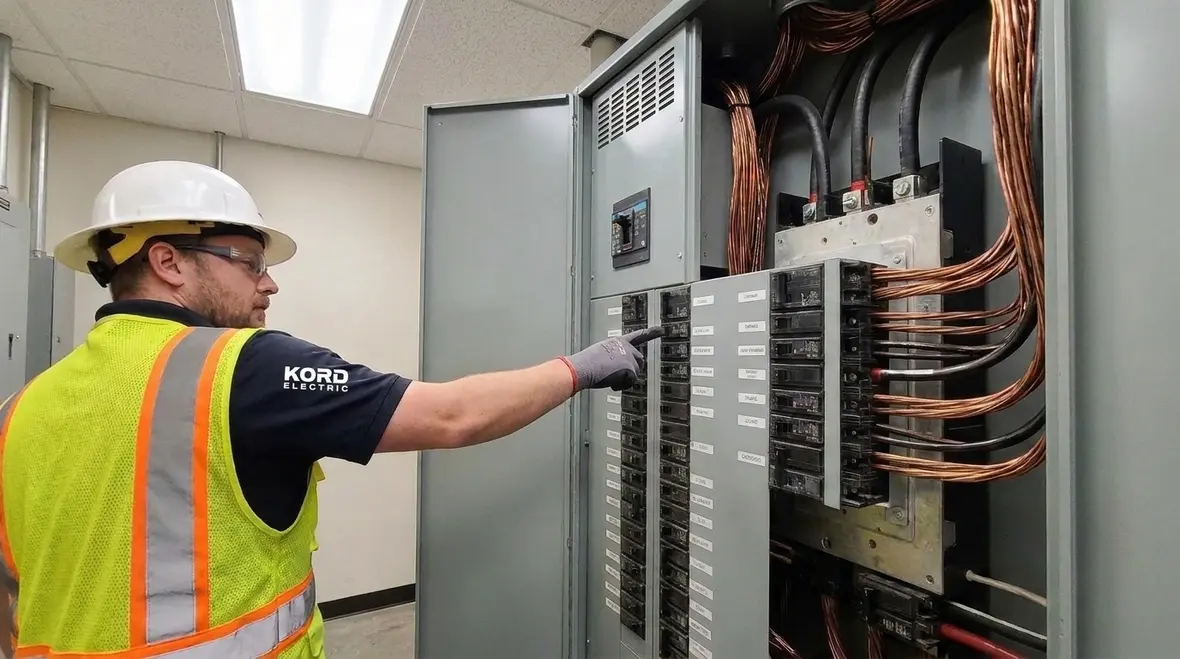
Section 310.1 scope leads us into the real world, where conductors get installed in specific ways. And that means the NEC conductor sizing scope keeps us honest about installation details. We see this often in places like distribution areas, plant expansions, and renovation projects where existing pathways constrain the new work.
Here are the installation factors we watch closely when we size conductors for commercial and industrial systems:
- Wiring method: raceways, cables, trays, and exposed runs change heat dissipation behavior
- Number of current carrying conductors: more conductors together often means added heat
- Insulation type and rating: insulation limits guide maximum permitted loading
- Ambient conditions: warmer spaces can force conservative conductor choices
- Bundling and proximity: crowded routes raise thermal interaction
Then we connect those factors to the protection scheme. A correctly sized conductor with mismatched protection can still cause trouble. So, we avoid the classic scenario where someone picks wire based on a quick look and then protection devices refuse to cooperate later. That is not a plot twist you want in a building occupancy schedule.
Coordination with overcurrent protection and circuit performance

After we size conductors under the conductor sizing scope, we verify how the entire circuit behaves. That means we check overcurrent protection and ensure it works with the conductor limits. In practice, this affects things like voltage drop, fault behavior, and how systems respond during abnormal events.
Additionally, commercial and industrial facilities run equipment that demands stable power. If we size conductors without considering coordination, voltage drop increases and equipment performance can drift. Over time, that drift shows up as complaints, downtime, and the kind of blame that sounds like a reality show but costs like an outage.
Our technicians and expert service staff help teams understand what coordination means in plain terms. We show how proper conductor sizing supports:
- Safer fault clearing by matching conductor limits with protective devices
- More stable operations by controlling voltage drop and heat
- Cleaner inspection outcomes through traceable calculations and documentation
And when owners ask, “Why can we not just upsize everything,” we answer honestly. Upsizing can help, but it can also increase cost, space demands, and installation complexity. So, we balance compliance, performance, and build constraints.
Common mistakes we help facilities avoid
Even smart teams make mistakes. And when those mistakes happen, the fix is rarely cheap. So, we focus on the errors we see most in commercial and industrial settings.
First, some teams forget that conductor sizing depends on installation conditions, not only the load current. Next, they may use incorrect temperature or bundling assumptions. Then they may mismatch wiring method details with the ampacity table selections. Finally, they sometimes skip documentation, which creates friction during inspection and maintenance planning.
Our experts at Kord Electric guide projects so the NEC conductor sizing scope remains consistent from design to install. That means we review assumptions, confirm wiring methods in the field, and keep calculations organized for audits and future service.
Because we support commercial and industrial facilities and major property buildings only, we see patterns tied to high demand environments: dense pathways, phased construction, and frequent equipment changes. Therefore, we build conductor sizing decisions that can handle growth, not just the day the electrician finishes the run.
Using our service approach for reliable NEC conductor sizing scope implementation
We bring order to the parts of projects that usually feel chaotic. When our team works with property managers, engineering teams, and facility leads, we explain each step and tie it back to the NEC conductor sizing scope and practical wiring realities.
Our service staff often starts with these actions:
- Review project requirements and verify load assumptions
- Confirm wiring methods and installation details that affect ampacity
- Check conductor ampacity and derating conditions based on thermal limits
- Coordinate protection devices and confirm circuit behavior
- Document decisions for inspections and future troubleshooting
And yes, we use a calm voice during stressful meetings. No one gets hurt when the plan makes sense. If you have ever seen a dramatic “someone grab the laptop” moment, you know what I mean. We prefer fewer surprises and more clarity.
NFPA 70 Section 310.1 and major building needs
Major property buildings have one shared trait: complexity. Therefore, we treat conductor sizing as part of an overall electrical strategy. Section 310.1 scope matters because it sets the foundation for conductor sizing rules used in that broader strategy. When we apply it properly, we reduce the chances of thermal issues, mis-coordination, and rework that delays tenants and impacts operations.
In addition, commercial and industrial systems rarely stay static. Equipment adds, loads shift, and mechanical upgrades come in waves. So, we help teams size conductors in a way that supports reliable performance as the building evolves.
To support ongoing electrical code education, Kord Electric also points teams toward broader NEC context resources. You can explore code explained for 2026 and other electrical guidance on our blog and partner pages such as Kord Fire and Fire Pumps. While we focus on implementation for commercial and industrial projects, the underlying code concepts stay consistent and the practical results matter.
When conductor sizing connects to larger retrofit and upgrade work, we also align our approach with project-level planning. For example, during major infrastructure upgrades we often coordinate NEC conductor sizing scope decisions with broader efforts like commercial electrical infrastructure projects planning, design, and execution, so the conductors, panels, and protection strategy all evolve together instead of in isolation.
FAQ
Conclusion and call to action
When teams understand the NFPA 70 Section 310.1 scope, they size conductors with confidence, not guesswork. At Kord Electric, we guide commercial and industrial projects through the NEC conductor sizing scope step by step, then we verify ampacity, installation conditions, and protection coordination so the system works the way it should. If you are planning new work, expanding capacity, or upgrading a major facility, reach out to us now. We will help you get it right the first time, with clarity and calm.
If your next project involves significant upgrades or a new distribution layout, our team can also pair NEC conductor sizing scope work with broader Los Angeles County commercial and industrial electrical services, so design, installation, and long term maintenance all line up under one coordinated plan.