NFPA 70 Section 326.24 NEC USE Cable Bending Radius You Can Trust
NFPA 70 Section 326.24: NEC USE cable bending radius you can trust on real jobs
At Kord Electric, we teach our customers to respect the NEC USE cable bending radius from the start, because cable does not bend like a story you can retell without consequences. In the first place, NFPA 70 Section 326.24 lays out how much a cable can turn before its insulation, jacket, and internal conductors start paying the price. Then, when facilities ignore those limits, problems rarely announce themselves with a drumroll. Instead, they show up later as overheating, damage at terminations, or failures that drain time and budgets.
We know facility teams want clear rules they can apply, not vague “be careful” advice. So, in this guide, our expert service staff explains the requirements in plain business language, while we also cover what technicians look for in the field. If you have ever watched a cable get forced into a tight turn like it is trying to escape a bad decision, you already know why these rules exist.
What Section 326.24 actually requires for cable turns
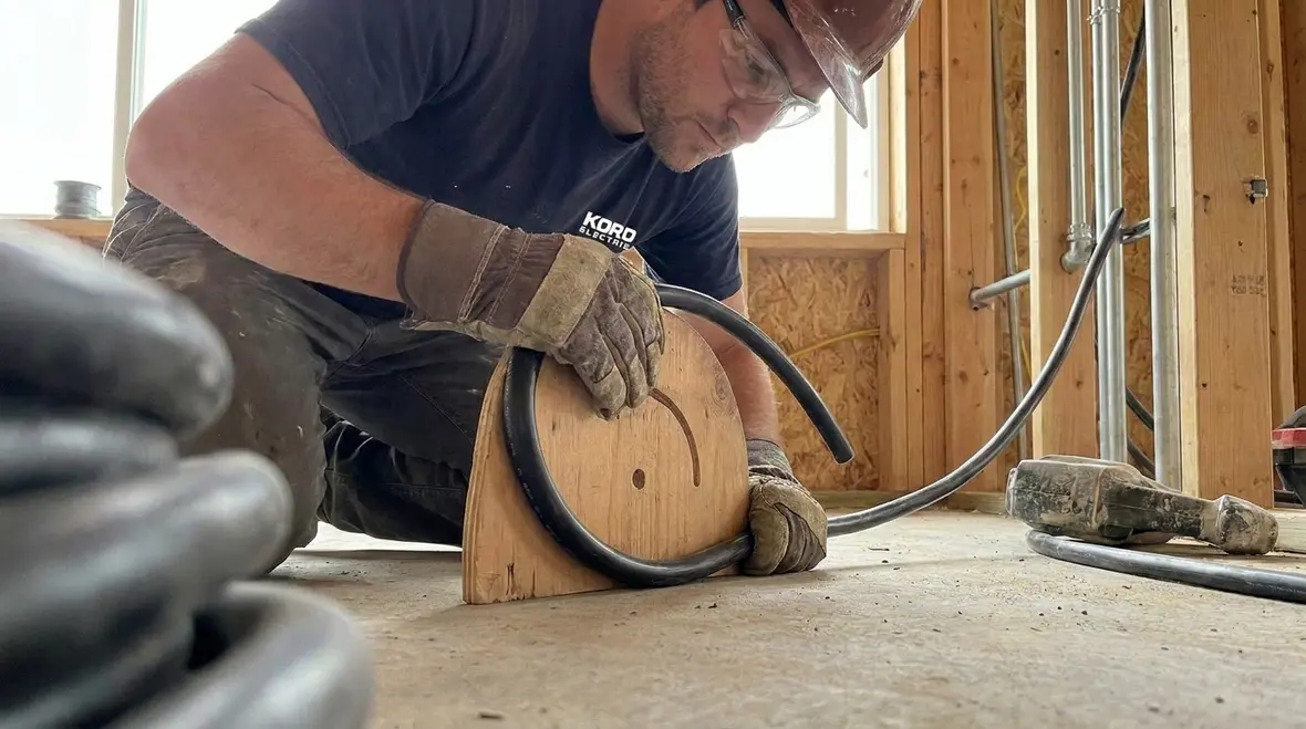
Section 326.24 in NFPA 70 focuses on use cable bending radius. More importantly, it sets boundaries that help prevent mechanical damage during installation. In other words, the rule treats bending limits as part of the safety system, not a cosmetic detail for tidy routing.
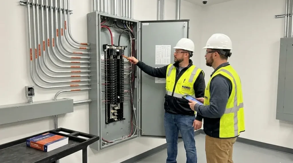
Our technicians work under the same principle across commercial and industrial facilities and major property buildings. First, they plan the route. Next, they measure the space where the cable must travel. Then they follow the required bending radius so the cable maintains its designed structure.
To say it more directly, forcing bends beyond the permitted limit is like putting a new roof on top of a shaky foundation. Everything might look fine during the install, but the stress builds quietly, and the bill comes later.
This is where Section 326.24 stops being “just text” and turns into a real constraint on how work gets done. It tells you, in effect, that every bend is a design decision, not a convenience. The bending radius you choose influences insulation performance, termination quality, and how long the system can be trusted to operate under load without creating hidden weak points.
At Kord Electric, we also make sure our field teams align with the bigger NEC picture, not just one section number. When we route USE cable, we connect Section 326.24 to overall wiring method requirements, working space rules, and equipment clearances, the same way we do when we apply guidance from NFPA 70 Section 90.2 on scope or Section 110.26 on working space around equipment. That broader view keeps a single bend from turning into a system-level problem.
How bending radius affects insulation, conductors, and long term reliability
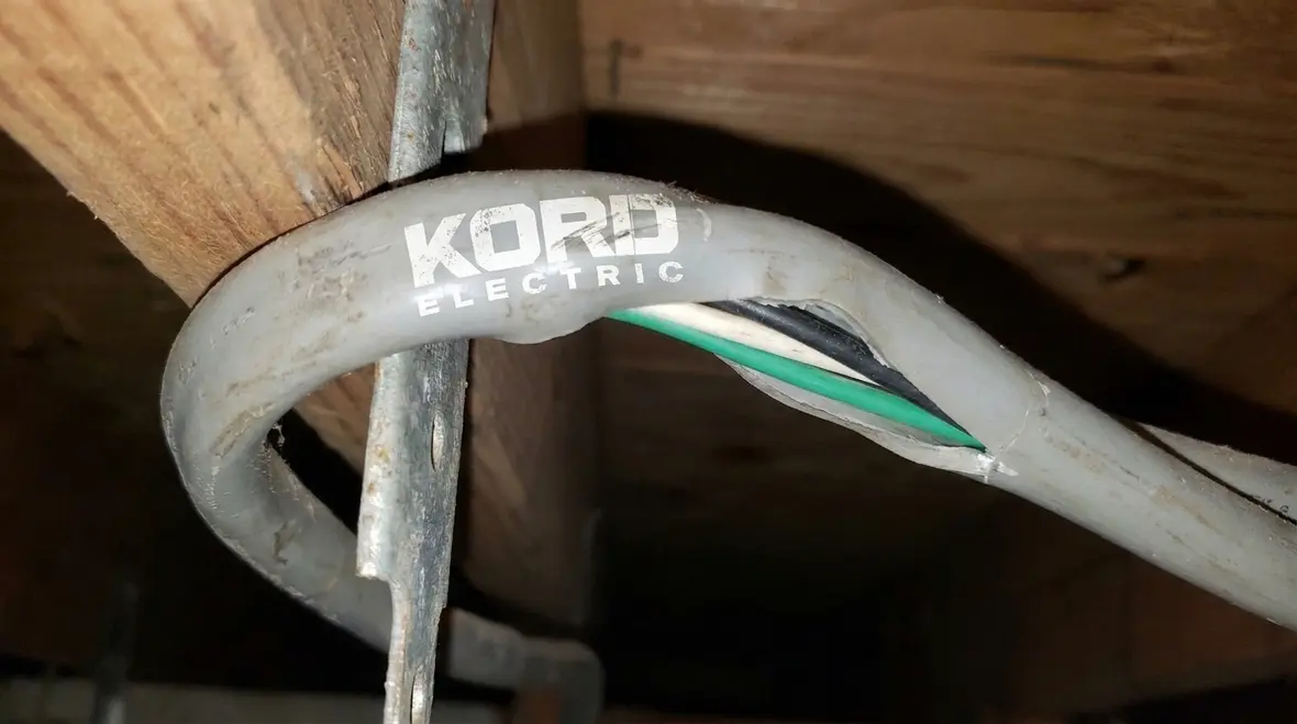
When cable bends too tightly, the stress does not stay politely at the bend. Instead, it spreads through the length of the cable in ways that can weaken the insulation over time. As a result, the insulation system can handle less load than it should, and that increases heat and stress at the conductor level. Furthermore, bends can cause jacket damage that invites moisture in harsh environments.
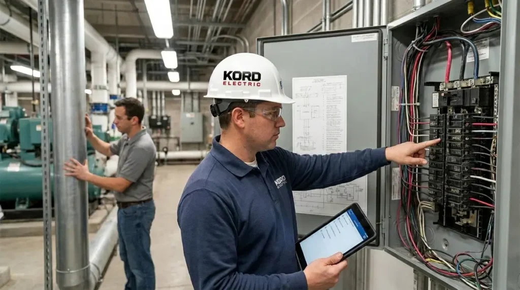
For commercial and industrial facilities, we see the downstream effects during commissioning and later maintenance. Technicians may notice issues at terminations, abnormal insulation resistance readings, or signs that a cable experienced mechanical strain. Then, while the team scrambles for answers, the real problem often traces back to install practices.
Our expert service staff explains this to owners in a calm, practical way: bending radius is not just a number from code. It is a protection rule for the whole electrical system.
In real projects, we have seen tight bends show up most often near pull points, at terminations, and where space was “borrowed” from nearby systems to make a routing decision work. Those choices might keep the schedule moving, but they also preload the cable with unnecessary mechanical strain. Over time, that strain can combine with elevated temperatures, harmonics, and load changes to push insulation right up to its failure point.
That is why our teams walk facility managers through how the NEC treats cable as part of the safety backbone. The same code that explains working space clearances, visible disconnect requirements, and branch circuit scope also assumes your bending radius choices will not undermine the system. When we point clients to resources like our National Electrical Code explained for 2026 guide, it is to reinforce that each detail, including bend radius, fits into a much larger safety story.
Field planning: measuring routes, using pulling methods, and avoiding “tight bends” surprises
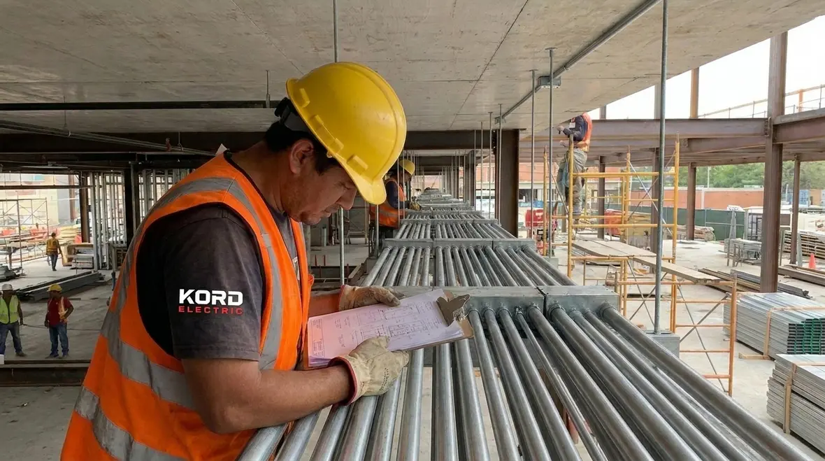
Even with correct paperwork, the job site can get chaotic fast. Therefore, Kord Electric emphasizes planning before the cable ever leaves the reel. Technicians start by reviewing the cable type, the route, and the work space conditions. Then they identify where directional changes happen, including offsets, corners, and transitions near panels and raceways.
After that, they choose pulling methods that support the bending limits. For example, if the route forces a sharp change, we look for ways to adjust the path instead of bending the cable harder. We also consider bend direction, because where the stress concentrates matters for long term performance.
Here is where a simple mistake can feel like pop culture plot armor. A contractor might think “We will make it fit,” like a superhero sliding through a door that is clearly too small. But electrical systems do not break the rules for entertainment. The cable either respects the NEC USE cable bending radius or it pays for the decision later.
Our planning conversations often include both design staff and field supervisors, because the NEC does not care who drew the line on the plan set. Once the work starts, the team on site must translate drawings into routes that physically respect the bending radius, clearance, and working space rules. That means flagging conflicts early, not waiting until the last hour of a shutdown window to announce that a panel wall is too close or a tray turn is too tight.
We also coach facility teams to treat cable handling like a quality control step, not just a labor task. Reels need proper support, pulls need controlled tension, and the people on each end must communicate when a bend is approaching. When our crews pull USE cable through complex runs, we apply the same discipline we use when we design around NEC working space and “in sight from switch” rules: no guessing, no assumptions, and no shortcuts that leave stress hiding in the walls.
Installation in conduit, trays, and raceways: what changes in practice
Facilities often route cables through conduit systems, cable trays, or a mix of both. Consequently, installation details change based on the enclosure and support method. In conduit runs, technicians focus on controlling the cable path as it enters fittings and bends. In trays, they focus on support spacing and ensuring the cable does not sag or kink when it passes around structures.
Also, the bending radius rules tie into how technicians handle corners and offsets. They must prevent the cable from snagging at the conduit wall or dragging across sharp edges. That means proper fit, smooth transitions, and correct installation tools.
To keep this practical, we once used a dual review approach with a large commercial project team: one column to track route geometry and one column to track compliance checks. It reduced rework and helped us explain the logic to stakeholders without turning the meeting into a lecture.
Route geometry checklist
- Identify every corner, offset, and transition point
- Measure available space for bend locations
- Verify raceway support and routing path
- Confirm access for pulling and pulling tension control
Compliance and install method checklist
- Verify the cable type and its bend limit guidance
- Plan pulls to avoid side stress and kinks
- Use tools and procedures that protect insulation
- Inspect bends before terminations and energization
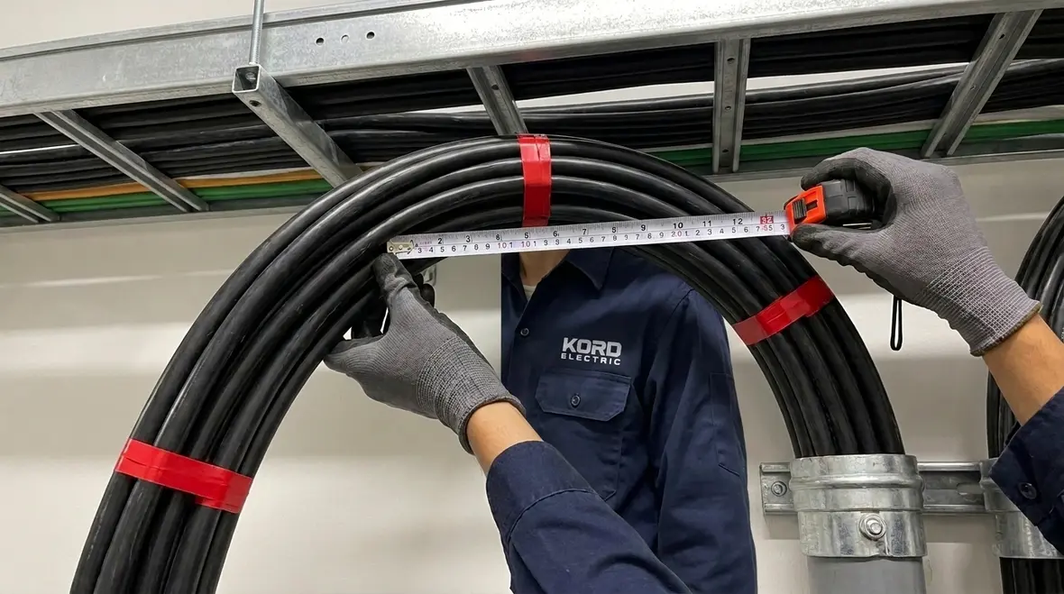
On many projects, we also coordinate bending radius decisions with tray fill, conduit size, and equipment layout. For example, it does little good to size a raceway correctly if the first 90-degree turn out of a pull box forces the cable into a bend tighter than Section 326.24 allows. Our crews use field measurements, not just drawings, to confirm that space exists for each turn and that installed hardware supports the required radius.
This is where good planning and strict adherence to NEC working space and routing standards pay off. A well-designed run gives every cable enough room to turn without crushing insulation or pinching jackets. That approach might mean slightly longer routes or different tray elevations, but it keeps the system aligned with both the letter and the spirit of the code.
Common failure points we prevent during inspections
When we send our technicians to inspect installs, we look for patterns that often link back to bending stress and poor handling. First, we check for signs of jacket deformation near bends. Next, we examine cable stress at entry points into enclosures, cabinets, and fittings. Then we review the route for sharp, improvised changes that do not match the planned path.
We also watch for “workaround” behavior. Sometimes teams try to correct a routing error by forcing extra bend or shifting where the cable turns. In the short term, it can hide the problem. However, in commercial and industrial facilities where uptime matters, hidden stress is still stress.
Our expert service staff documents what they see and explains what it means for reliability. That is important because many facility managers do not need a textbook. They need a clear path to protect assets and reduce downtime risk. And honestly, no one wants surprise outages that start at the bend nobody wanted to redo.
We have seen failures show up months or years after energization, when a combination of temperature cycles, vibration, and load change finally exposes what the tight bend started. In those moments, having photos and documentation from the original install makes it much easier to connect the dots and correct the underlying issue instead of just swapping components at the failure point.
That is why we treat NEC USE cable bending radius rules the same way we treat branch circuit scope or equipment clearance requirements: as non-negotiable design inputs. When our team references NEC explainers and NFPA 70 guides from our own Kord Electric and Kord Fire resources during inspections, it is to reinforce that the code already predicted many of the “mystery” failures people see in the field. The solution is to follow those rules on the first pass, not on the third outage.
Coordinating with the broader NEC and project compliance
Section 326.24 does not live alone. It sits inside a larger NEC framework that covers how electrical installations must be safe and dependable. For that reason, we align the bending radius practice with project compliance goals such as proper installation methods, safe routing, and correct device and termination setups.
Additionally, Kord Electric supports teams that need coordinated work across electrical systems. While some projects include multiple scopes, we keep the focus on the practical outcome: stable installs that pass inspection and perform under real operating conditions.
If you want extra context on how the NEC is structured and how code explanations translate to real sites, our team also references NEC guidance and industry learning resources at Kord Fire and related organizations. For example, the approach you see in NEC explainers at Kord Fire’s NFPA 70 overview emphasizes that code must connect to field practice. And for facilities that work with pumps and life safety systems, resources that explain how electrical reliability supports fire pumps help teams connect bending radius and wiring details to the performance of systems that matter.
On many commercial and industrial jobs, our technicians use a simple mental model: every NEC rule either protects people, protects property, or protects both. Bending radius fits right beside rules about disconnect visibility, equipment clearances, and branch circuit scope. Each one tightens up a different part of the risk picture. When they all align, projects move smoothly through inspections and stay reliable under real-world loads.
That is also why we encourage facility leaders to treat NEC training as part of their long-term maintenance strategy. Articles that explain how to read NFPA 70, how to interpret the 2026 NEC scope, and how to understand sections like 90.1, 90.2, and 90.6 give teams a way to see bending radius not as an isolated demand, but as one piece of the overall electrical safety framework their business depends on.
FAQ: NFPA 70 Section 326.24 and bending radius for cable
Conclusion: call Kord Electric before the cable hits the corner
If your facility team wants electrical installs that stay reliable, we recommend involving Kord Electric early, before routing decisions get locked in. Our technicians and expert service staff plan cable paths, verify bend handling, and help protect the system long before commissioning. That means fewer rework cycles, less downtime risk, and a smoother path to compliance for commercial and industrial facilities and major property buildings. Reach out to Kord Electric today and let us help you install with confidence, not hope.
For projects across Los Angeles County and surrounding regions, our commercial and industrial electrical services team applies the same NEC-focused approach to planning bends, sizing raceways, and protecting working space that we use on every code-driven upgrade. When you combine smart routing, correct NEC USE cable bending radius, and disciplined inspections, you get an electrical system you can trust when shifts are busy and downtime is expensive.