NFPA 70 Section 630.11 Welder Supply Ampacity Guide
NFPA 70 Section 630.11 welder supply ampacity sets a practical rule for how much current an electrical system must safely carry to feed welding loads. At Kord Electric, we tell our commercial and industrial clients the same thing we tell our own crews: when you get this part wrong, you do not get a “small mistake.” You get heat, wear, and downtime. And nobody wants that kind of drama, not even the actors on your latest workplace streaming binge.
In this guide, we explain how the National Electrical Code treats welding and related feeder and branch circuits, especially where equipment and loads connect in real facilities. Then we show what our expert service staff checks on site, how we document compliance, and why good design work now beats emergency repairs later.
NFPA 70 welding supply basics for commercial sites
Third person reading this can still feel like we are talking directly to the power room, because that is where the real story lives. The NEC includes specific direction for welding loads, and NFPA 70 Section 630.11 welder supply ampacity gives a baseline method for sizing conductors and ensuring the system can handle the load without unsafe temperature rise. In other words, the code does not guess. It expects the design to follow measurable requirements tied to welding equipment demand.
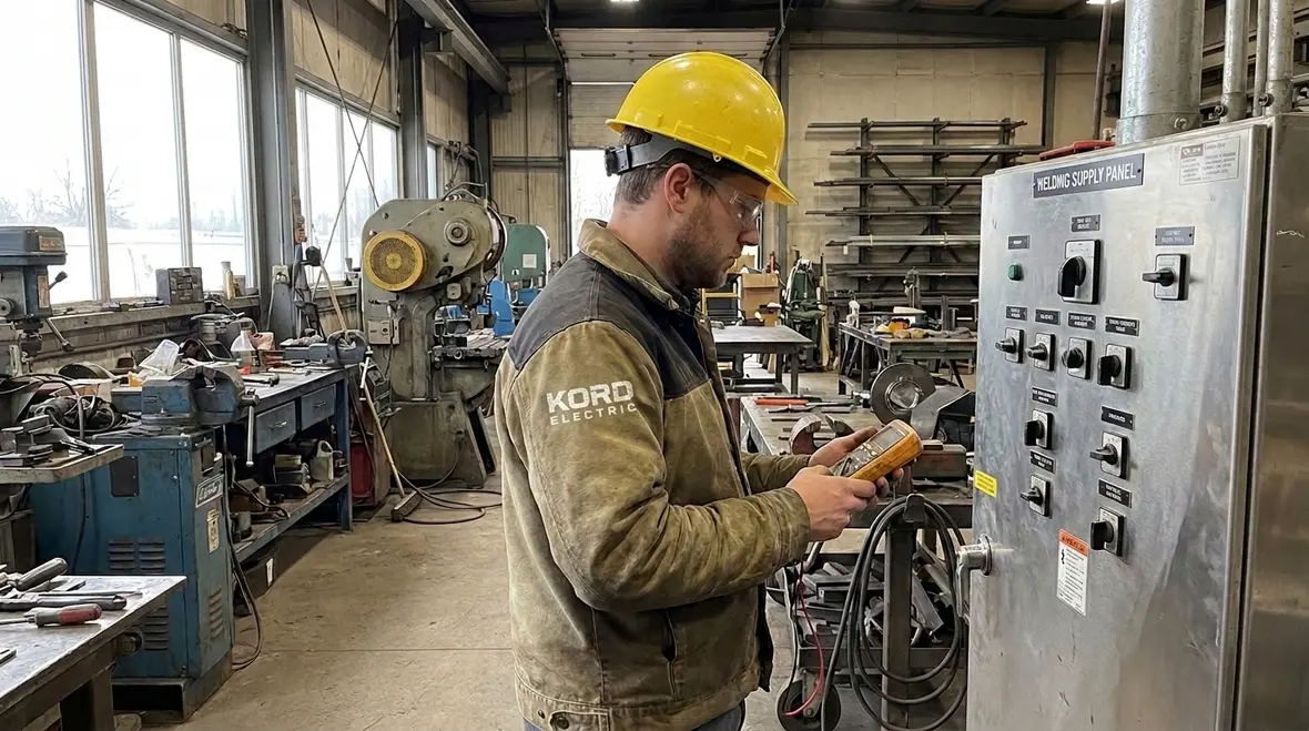
To keep the pacing steady, Kord Electric and our technicians start with the operating plan. Welding is not one simple current draw. It changes as work shifts from one task to the next, and it can vary by duty cycle, electrode type, and machine settings. So, even when the installation looks “finished,” it still needs a load logic that matches how the facility actually runs.
Next, we connect that logic to NEC sizing steps. We verify whether the welding supply is treated as part of branch circuit work or feeder supply work, depending on the system layout, then we confirm conductor size, insulation rating, and termination ratings. If someone tries to “make it fit” after the fact, that is usually when we hear the line, “We can just swap in a smaller breaker.” That line ends with us politely explaining why it fails under code intent.
For teams that want a broader backdrop before zooming into welding specifics, Kord Electric’s own NEC primer helps connect the big-picture code rules to decisions in the field. Their guide on what NFPA 70 covers in practical terms walks through how the rulebook shapes wiring, overcurrent protection, grounding, and equipment installation, then ties those ideas back to real buildings across Los Angeles County and Southern California.
How NEC load rules affect welding feeders and conductors
When a facility adds welding equipment, other electrical rules suddenly matter more. Designers must coordinate welding loads with the rest of the building system so the upstream components can support the combined demand. Therefore, the electrical design cannot treat welding as an isolated island.
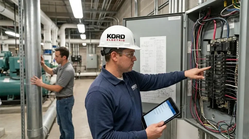
Kord Electric’s expert service staff approaches this like a system check, not a scavenger hunt. We examine panel schedules, existing conductor sizes, bus ratings, and the short circuit and ground fault protection strategy. We then look at how the new welding loads connect to those systems.
Next, we compare the calculated ampacity basis to actual equipment nameplate values and installation conditions. Conductor ampacity depends on more than current. It also depends on ambient temperature, number of conductors in a raceway, insulation type, conductor material, and installation method. If the installation environment makes conductors run hotter, the code expects compensation through correct sizing or adjustment factors.
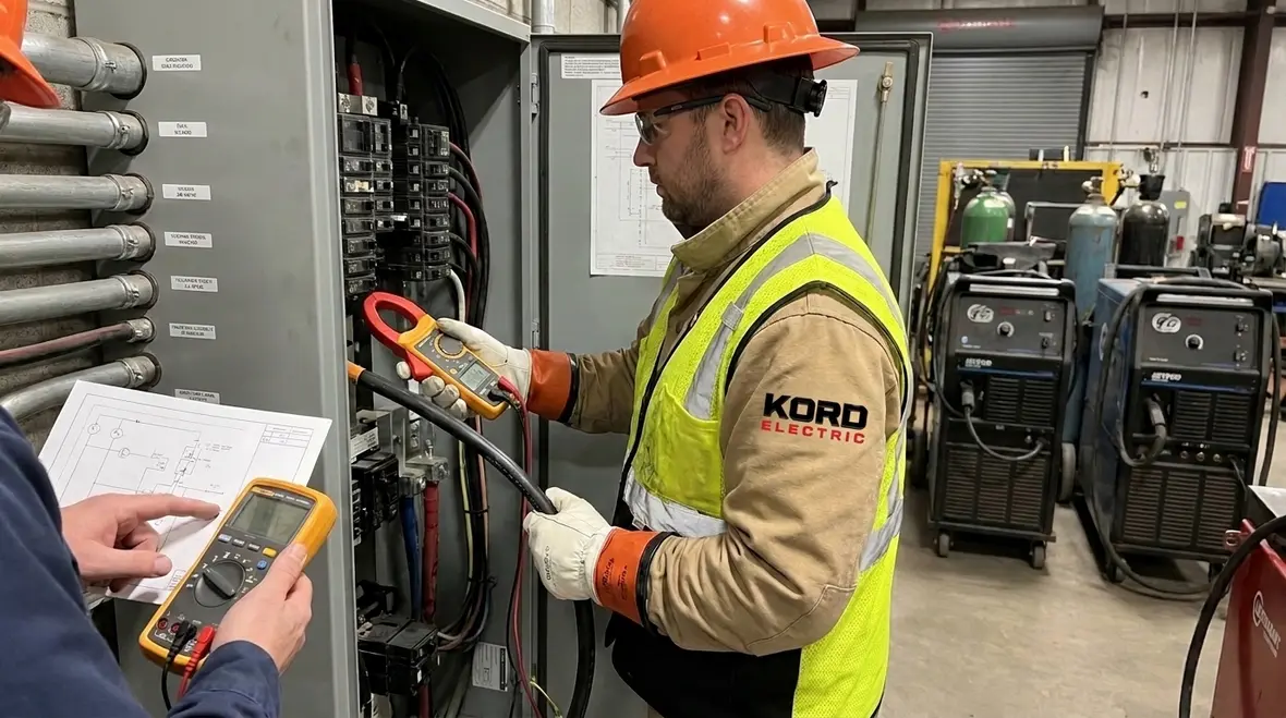
Meanwhile, terminations must match the conductor and the equipment rating. A system can be correctly sized on paper and still fail in the field if torque settings, lug selection, or wire preparation are off. Our technicians use calibrated tools and check terminal condition, because “almost tight” is not a rating anyone should bet a plant budget on.
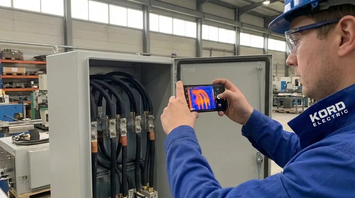
In larger projects, welding supply work often joins a cluster of code-focused upgrades. It is common for Kord Electric to evaluate how welder feeders interact with other branch circuit rules, such as those governing individual branch circuit loads or multiwire branch circuits, so the total design stays aligned with NFPA 70 rather than treating each section like a separate universe.
What our technicians verify during NFPA 70 compliance checks
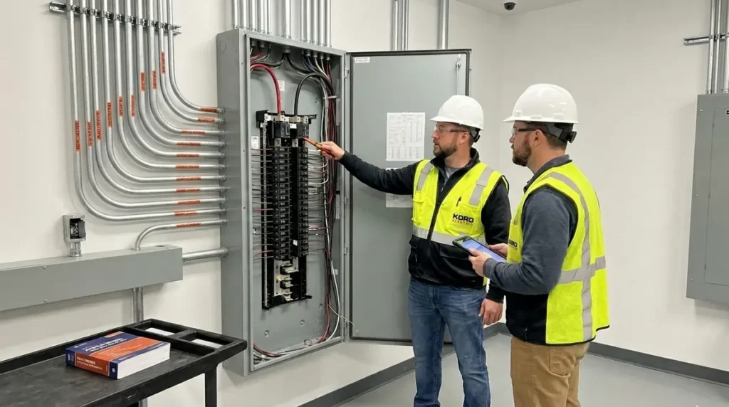
Now comes the on site reality, where drawings meet dust and steel. Kord Electric serves commercial and industrial facilities and major property buildings, so we plan our checks to reduce downtime. We also explain results in plain language so the facility team can make confident decisions.
Our technicians typically verify these areas when welding supply circuits get added or upgraded.
- Circuit identification so welding feeders and branch circuits match the documentation and the labels in the field
- Conductor sizing to align with NFPA 70 Section 630.11 welder supply ampacity direction and the rest of the NEC ampacity logic
- Overcurrent protection coordination so breakers and protective devices match the conductor ampacity and the equipment requirements
- Termination quality including lug type, torque, wire stripping length, and conductor surface condition
- Raceway and installation conditions such as conductor fill, ambient temperature, and insulation suitability
- Grounding and bonding continuity to keep fault paths predictable and safe
And yes, sometimes we find issues that started as “temporary.” For example, a welding circuit tied into a panel bay that was never meant for that duty profile. Then the facility wonders why components age faster than the rest of the building. We explain that electrical systems behave like machines with memories. They remember every time they got pushed beyond their design comfort level.
During these checks, our crews also flag opportunities to bring documentation and diagrams up to modern expectations. When new welding feeders are added, we align them with updated one-line and feeder diagram practices, so your maintenance staff is not left hunting through outdated prints years from now.
Common design mistakes we prevent for welded power systems
Many electrical failures do not come from one huge error. Instead, they come from small shortcuts stacked like late night snacks. Kord Electric’s expert team often sees recurring mistakes that drive call backs.
First, facilities sometimes undersize conductors because they only look at one operating point of the welder. Welding loads swing. So the proper approach uses the code method for welding supply sizing and then considers installation conditions. When the design uses welder supply ampacity reasoning too loosely, the conductor temperature rise becomes the villain.
Second, teams sometimes mismatch protective device ratings. They may select a breaker based on general panel size rather than the conductor and welding load requirements. However, the NEC expects coordination between conductors and overcurrent protection. So we check that alignment and document it clearly for the facility.
Third, the installation environment matters. A conductor run in a tight raceway in hot equipment rooms does not behave the same as one in a cool open area. Adjustments and correct installation method matter, and the code accounts for those realities.
Finally, termination issues can sneak in even with correct sizing. Poor lug selection, wrong wire prep, or inconsistent torque can create hot spots. Hot spots grow, and then the facility pays for it with nuisance trips or premature failures. Our technicians follow a repeatable checklist so the work stays consistent across shifts and teams.
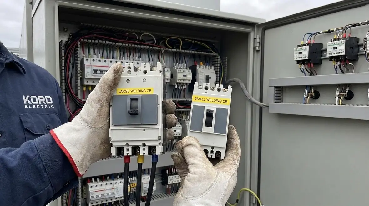
When we talk about these mistakes with facility teams, we keep the tone calm and practical. The goal is not blame; the goal is a system that handles work shifts, expansions, and inspections without turning every outage into a cliffhanger.
Real world coordination with other building electrical systems
Commercial and industrial facilities carry complex electrical networks. Therefore, welding power upgrades must coordinate with upstream service capacity, generator or UPS arrangements, and other high demand loads. Kord Electric plans upgrades with the full electrical picture in mind, not just the welder circuit.
In a typical major property building, welding loads sit alongside HVAC equipment, lighting systems, process equipment, and sometimes motor dominated loads. So the electrical engineer or contractor must consider how the building load profile changes. Even if the welding supply meets the ampacity basis, a facility can still see voltage dips, nuisance protective device trips, or generator stress if other parts of the system design do not match the new demand.
Additionally, modern facilities need a clean commissioning handoff. We verify circuit operation, check insulation resistance where appropriate, confirm phase balance if required by the setup, and ensure labeling supports maintenance staff. Others can install the circuit. We focus on making sure it stays reliable when the facility changes shift schedules and equipment layouts.
If a client references the broader NEC and fire related code resources, we help them connect the dots. For example, KordFire resources discuss how NEC relates to fire and electrical safety outcomes at a practical level. Kord Electric then translates that into specific design and field checks for welding power.
On multi-phase projects, we often pair welding circuit upgrades with broader electrical resilience work. Examples include emergency power planning for offices, NEC grounding improvements, and corrosion protection in harsher spaces. That coordination keeps the entire system moving forward together rather than in disconnected pieces that surprise the operations team later.
Using NEC and local safety guidance for welding equipment
Codes exist to protect people and property, and NEC is one of the central documents used in the electrical design process. However, it does not stand alone. Facility teams also face local requirements, AHJ interpretation, and project specific standards used by insurers or building owners.
Kord Electric stays focused on commercial and industrial installations, which usually means we work in environments with strict safety protocols and ongoing operations. That is why we document our compliance steps and explain the “why” behind the “what.” When the facility team understands the logic, approvals happen faster and maintenance runs smoother.
We also recommend clients review related safety resources, including NEC discussions and fire safety guidance from partners in the code ecosystem. For example, KordFire and firepumps related industry resources explore how electrical and life safety planning connects in real buildings. Even when a project focuses on power distribution, the safety outcome matters.
In short, the best result comes when electrical design and safety planning act like a single team. And if that sounds like a movie plot, it is. The difference is no one gets hurt, and the credits roll on schedule.
For facility managers who want an even deeper code backdrop behind welding work, Kord Electric’s companion article Understanding NFPA 70: The National Electrical Code Explained for 2026 connects the section-by-section requirements to real renovation and upgrade decisions.
FAQ for welding power circuits and NFPA 70
Schedule a code driven welding power assessment with Kord Electric
Kord Electric can assess your welding power circuits, verify NFPA 70 Section 630.11 welder supply ampacity alignment, and coordinate the upgrade with the rest of your electrical system. Our technicians explain findings clearly, document compliance steps, and focus on reliability for commercial and industrial facilities and major property buildings. If you are planning new welding equipment, expanding a shop, or seeing nuisance trips and heat related wear, reach out. We will help you build a safer, stronger electrical path for the work ahead, without the late night surprises.
If your facility is in or around Los Angeles County, you can also pair a welding assessment with broader upgrades through Kord Electric’s dedicated Los Angeles County commercial and industrial electrical services team, so code-driven improvements, capacity planning, and emergency power strategies all stay in sync.
For building owners mapping long term electrical strategy, combining a welder supply review with NEC-focused consulting and targeted service work turns welding circuits from a perceived risk into a well-documented asset. That way, the next time someone in the shop wants to add a welder, you are working from a plan, not a cliffhanger.
When you are ready to line up that next project, our team is here to help you keep the power steady, the code boxes checked, and the production schedule free of unwanted plot twists.
Ready to talk through your welding power circuits? Use the button below to connect with Kord Electric and schedule a NFPA 70-focused assessment that fits your operating schedule.