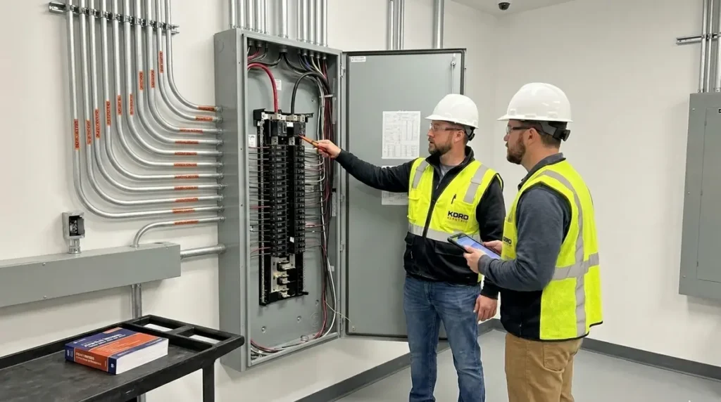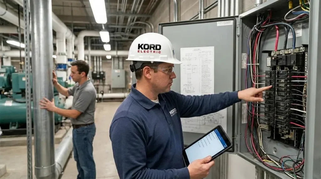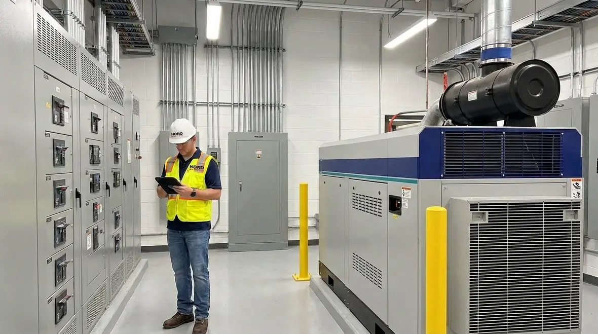
NFPA 70 Section 692.8 Fuel Cell Circuit Sizing Explained
NFPA 70 Section 692.8 fuel cell circuit sizing, explained for commercial and industrial sites
When a commercial or industrial building plans a fuel cell power system, the electrical design has to get very specific, very fast. In particular, NFPA 70 Section 692.8 fuel cell circuit sizing sets the rules that help us protect equipment, manage load, and prevent unsafe overcurrent conditions. We at Kord Electric focus on major property buildings and commercial and industrial facilities, and we treat these rules like the blueprint for safe power. Our technicians and expert service staff walk through the details carefully, because one “good enough” decision in design can turn into a long night for the maintenance team. And yes, we know the night shift already has enough drama without an electrical mystery.
In this article, we explain how the National Electrical Code, including the fuel cell sections and related protection concepts, fits into real projects. Then we connect it to practical steps our team uses in the field, from design review to installation coordination.
Why the National Electrical Code matters for fuel cell systems
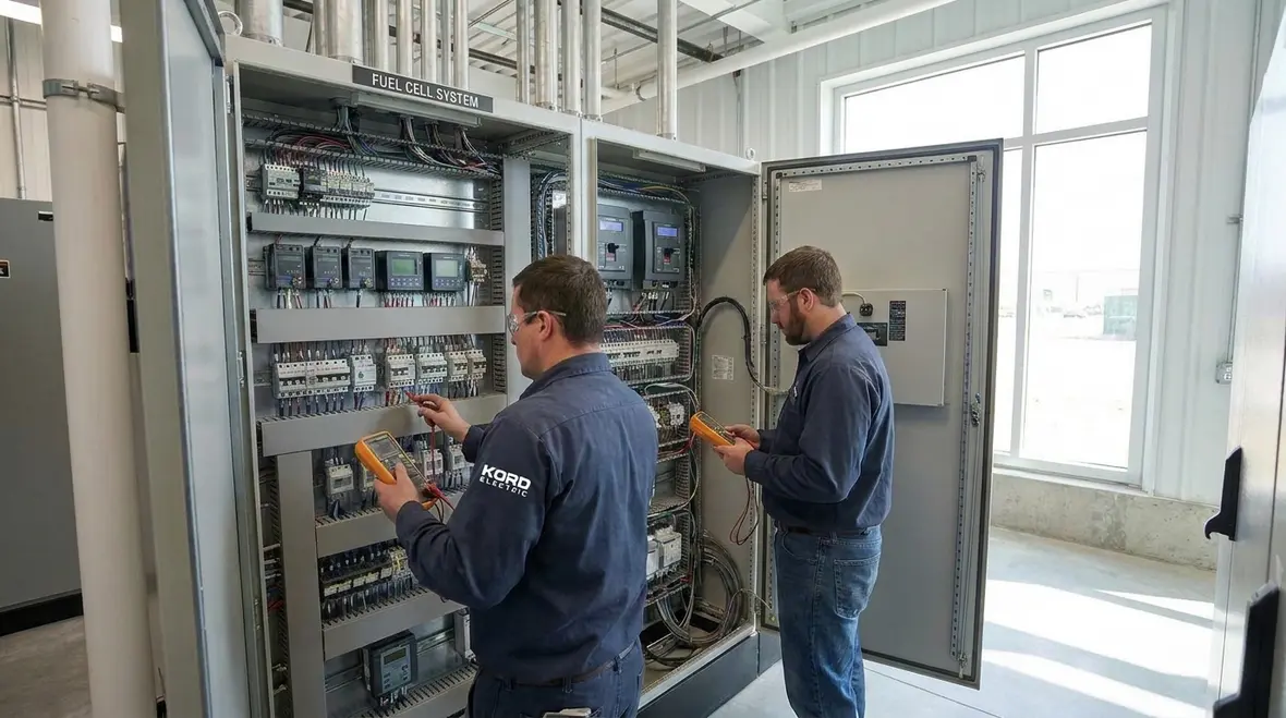
NFPA 70 is not a suggestion, it is the common language for safe electrical work. For fuel cells, the Code helps define how conductors, overcurrent protection, and circuit ratings should match the system’s output behavior. As a result, facilities that follow these requirements tend to avoid nuisance trips, unstable operation, and equipment stress. Meanwhile, teams that skip the details often discover problems at the worst possible moment, such as during commissioning or peak operations.
Kord Electric works with electrical designers, integrators, and facility managers. Therefore, we help translate Code intent into buildable steps. Our technicians explain the “why” in plain terms, so others on the project understand the logic, not just the rule.
If your team needs a broader NEC refresher while planning a fuel cell installation, resources like our guide on Understanding NFPA 70: The National Electrical Code Explained for 2026 help frame how the Code behaves across different building types before you zoom into the details of Section 692.8.
What Section 692.8 fuel cell circuit sizing requires in practice
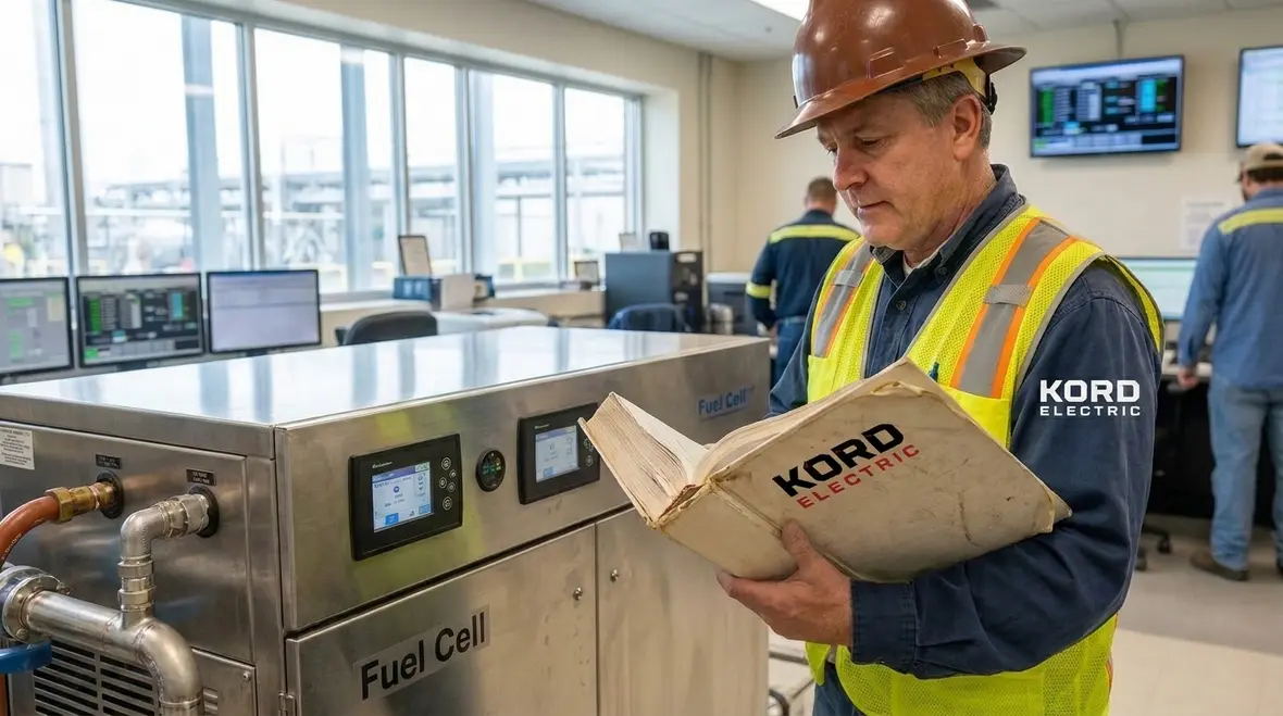
Section 692.8 fuel cell circuit sizing is where the Code gets very direct about how to size circuits that connect to fuel cell systems. It addresses how to account for the characteristics of the source, and it guides how protection and conductors should respond to expected electrical performance. Consequently, the sizing process cannot be copied blindly from other generation equipment. Fuel cell output behavior can differ from other sources, and the Code expects the design to reflect that.
In the field, we treat this as a checklist driven by documented data from the fuel cell manufacturer. Then we verify the design assumptions with engineering review and installation constraints. If documentation is unclear, we do not guess. Instead, our expert service staff helps gather the needed information early, so the final design aligns with NFPA 70 requirements and avoids costly rework.
Also, we keep an eye on how the circuit ties into the facility’s broader electrical system. That means we coordinate with switchgear, transfer equipment, and any standby power strategy. In other words, we size the circuit, and we also make sure it plays well with the rest of the building.
Translating NEC text into a real fuel cell one-line
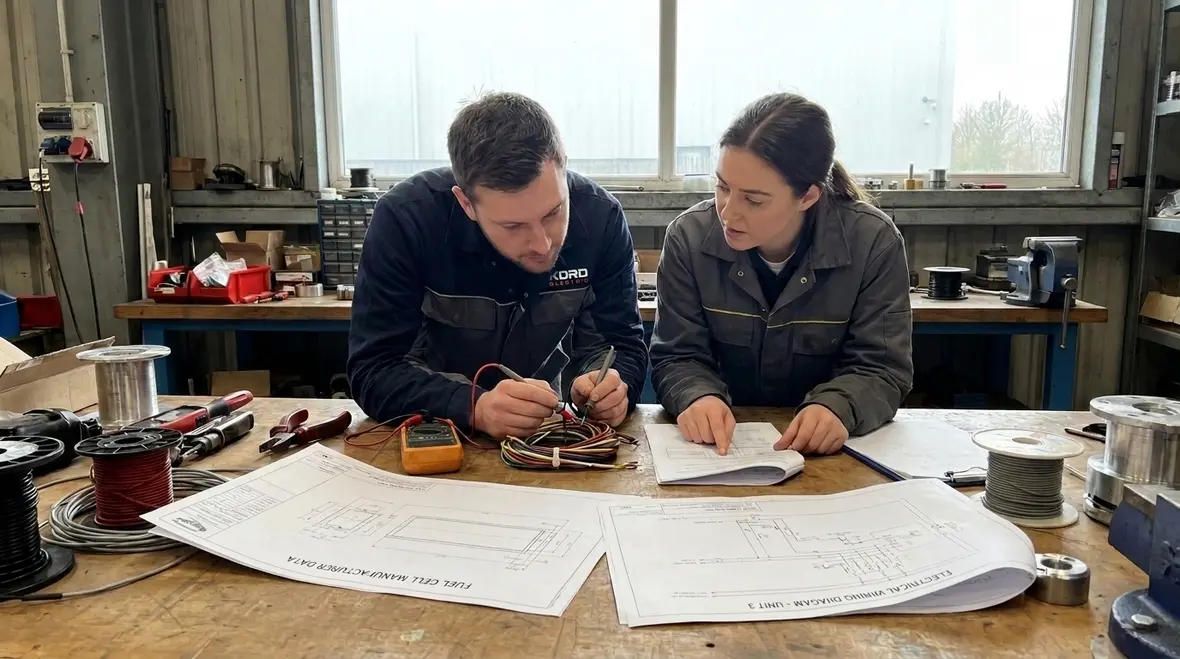
A lot of project teams first meet Section 692.8 fuel cell circuit sizing as a paragraph of text in the NEC. That is useful, but not enough. On an actual one-line diagram, we have to match those words to conductor sizes, breaker ratings, disconnect layouts, and interconnection details that live in real conduits and real rooms with very real space limits.
Our process usually starts with the nameplate and data sheets, then moves into calculations that match the fuel cell’s maximum current output and operating profile. From there we layer in ambient temperature, grouping, and routing constraints. Only when the math and the field conditions agree do we call the sizing complete.
Why fuel cell behavior changes the sizing conversation
Unlike some conventional generators, many fuel cell systems deliver a more stable, DC-based output that then passes through power conditioning equipment. That means we pay attention not just to raw current, but to how converters, inverters, and protection interact. NFPA 70 wants that behavior reflected in the conductors and overcurrent protective devices (OCPDs) you choose, not just in a pretty schematic during design review.
Building a safe circuit: conductors, protection, and coordination
After the sizing step, the next question becomes how the circuit stays safe under faults and abnormal conditions. Therefore, conductor sizing and overcurrent protection must align with the expected current levels and the way the fuel cell system behaves during different operating states. If the conductor is undersized, heat and voltage drop can become issues. If protection is not aligned, the system may fail to clear a fault quickly or may trip during normal operation.
Our technicians coordinate the full chain, from conductors and connectors to breakers, fuses, and protective devices. However, we also focus on selectivity and coordination. That matters most in major property buildings where one trip can disrupt multiple areas. When protection devices coordinate, a fault in one zone clears locally rather than causing a facility wide blackout.
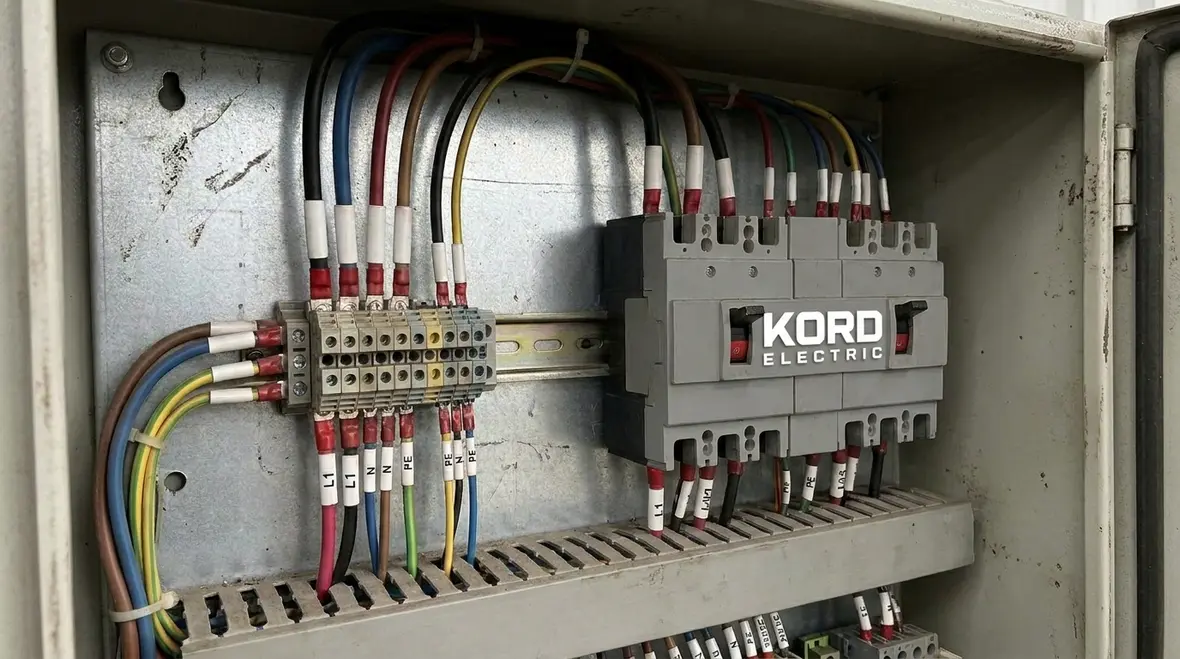
We also pay attention to labeling and documentation. As we move from design to installation, we make sure the as built record matches the sizing basis. Then, during commissioning, our team confirms continuity, polarity, and protective device settings. Because if nobody can trace what was done, maintenance becomes a guessing game, and nobody wants that.
From conductor ampacity to real coordination
Good fuel cell circuit sizing does more than hit an ampacity table. It also supports time-current coordination so that the right device trips first. If a fault occurs on a downstream feeder, you want that feeder’s OCPD to open without taking the main offline. For complex projects, we often pair Section 692.8 work with broader conductor and OCPD checks similar to those described in resources like our breakdown of NEC OCPD conductor protection, so the fuel cell does not become the odd device out in your protection scheme.
How NFPA 70 connects to system planning and project workflows
Many people read the Code like it is a standalone document. In reality, it sits inside a workflow. Designers build a concept, integrators select components, and contractors install and verify. Consequently, the Code shapes decisions at every stage. For example, the fuel cell circuit sizing influences panel schedules, cable routing, termination details, and commissioning tests.
Kord Electric supports commercial and industrial facilities with a process-driven approach. First, we review the electrical design documents against applicable NFPA 70 requirements, including the fuel cell circuit rules. Next, we coordinate field conditions, such as conduit fill limits, cable pulling distances, and equipment access for maintenance. Then we verify that the final build can support the operation the owner expects.
Meanwhile, we also help teams connect Code compliance with realistic schedule needs. If a project runs late, crews start skipping verification steps. We do not do that. Instead, our expert service staff builds verification points into the plan so the team stays on track without cutting corners.
And because pop culture is undefeated, we like to think of the Code like the script. You can improvise a little, sure. But when it comes to electrical safety, improv is how you end up in a cautionary YouTube clip titled “Why We Didn’t Test.”
Pairing fuel cell planning with broader NEC strategy
Fuel cell projects rarely happen in isolation. They land in buildings that also need emergency power, critical cooling, life safety loads, and day-to-day comfort systems. When we plan NFPA 70 Section 692.8 fuel cell circuit sizing, we often cross-reference broader NEC topics like grounding and bonding strategy, emergency power routing, and cable ampacity limits so the project does not pass one narrow test and fail the bigger picture.
Compliance support for major buildings and commercial operations
Commercial and industrial facilities often run continuously, and downtime costs real money. That is why our teams at Kord Electric and our broader safety focused group Kord Fire help align electrical safety with operational reliability. For projects that include fire pumps, suppression interfaces, and life safety systems, coordination becomes even more important. We ensure that electrical work does not create hidden conflicts with life safety requirements.
If a facility includes fire pump power supplies or related electrical controls, you cannot treat electrical systems like separate islands. You need coordination across disciplines. For additional context on related safety resources, we also reference materials like those found through firepumps.org and our own guidance at kordfire.com.au and kordfire.com, while staying anchored in NFPA 70.
We also focus on owner requirements. Some owners need detailed training for maintenance staff. Others need documentation tailored for inspections. Our service team supports both. Therefore, when others ask, we can explain what the sizing rules drive, how the protection works, and what tests confirm safe operation.
Fuel cells, fire pumps, and life safety systems on the same map
Where fuel cell projects overlap with fire protection, we coordinate closely with life safety requirements and fire pump power expectations. That means planning separation where needed, honoring emergency circuits, and making sure fuel cell output does not compromise the performance of systems designed to protect people and property. The Code helps define these boundaries; our job is to make sure they exist clearly on drawings, in conduits, and in the final as built package.
Planning, inspection, and commissioning steps we use on the job
Proper NFPA 70 compliance does not end with installation. It continues through inspection and commissioning. As a result, we build verification steps into the process so the project passes checks and operates as intended.
Here is how we typically approach it:
- Document review: We verify fuel cell output data and confirm that the NFPA 70 Section 692.8 fuel cell circuit sizing basis matches the design set.
- Protection alignment: We check that protective device ratings match the sized circuit and support proper fault clearing.
- Field install verification: We confirm conductor installation quality, terminations, and routing practices that keep voltage drop and heat under control.
- Commissioning support: Our technicians help verify functional operation and ensure protective settings follow the documented design.
- As built updates: We help keep records accurate so future inspections and troubleshooting rely on facts, not memory.
When we explain these steps, our expert service staff keeps it simple. They connect the Code requirement to what you can actually see in the panel, on the cable, and in the device settings. That clarity reduces friction between design teams, installers, and facility stakeholders.
From pre-energization checks to long-term reliability
After the first energization, the job is not really over. We encourage owners to fold fuel cell circuits into preventive maintenance plans, infrared scanning schedules, torque checks, and documentation reviews. That way, NFPA 70 Section 692.8 fuel cell circuit sizing does not just live in a design binder from year one; it stays connected to how the system behaves in year five and beyond.
For facilities across the region that want that long-term view, our work on fuel cell circuits fits naturally with broader electrical reliability efforts, including service offerings like Los Angeles County electrical services that support everything from design-build to maintenance and emergency response.
FAQ: NFPA 70 fuel cell circuit sizing and related compliance
Conclusion: Get Code aligned before you energize
Fuel cell installations can deliver strong benefits, but only when the electrical design follows NFPA 70 correctly. Kord Electric helps commercial and industrial facilities plan, review, and build systems that support NFPA 70 Section 692.8 fuel cell circuit sizing and related protection requirements. If you are building a new system or upgrading an existing power setup, contact us early. Our technicians and expert service staff will help you reduce risk, avoid rework, and move toward commissioning with confidence. Let’s get your project energized the safe way.