NEC Section 692.7 Fuel Cell Maximum Voltage for Safer Power
NEC Section 692.7 fuel cell maximum voltage sets the tone for safer power systems
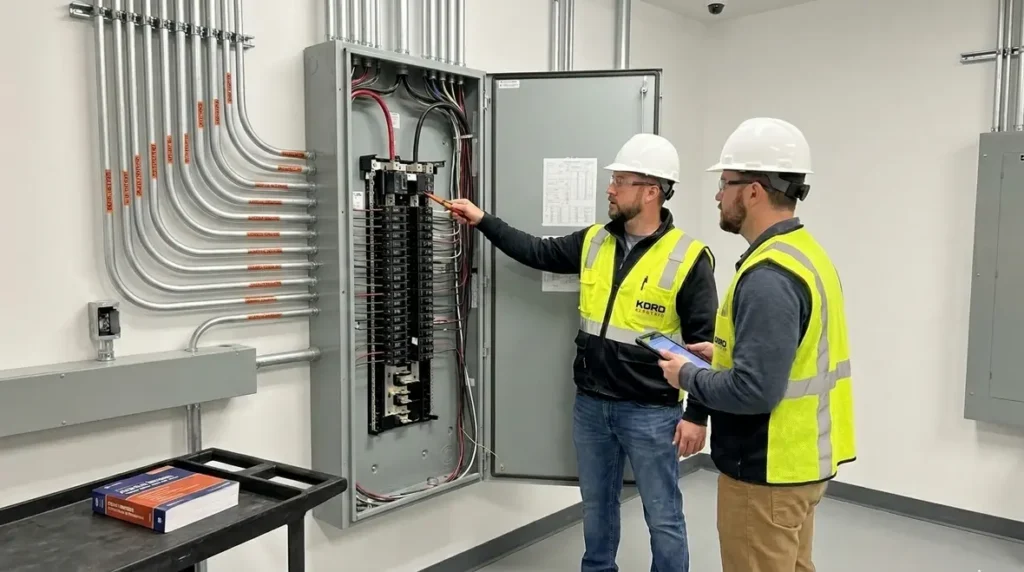
In commercial and industrial facilities, every new power option deserves a clear rulebook. That is why NEC Section 692.7 fuel cell maximum voltage matters early, not late. In many real projects, the first mistake we see is teams treating fuel cell wiring like a “plug and play” upgrade. Meanwhile, the code expects deliberate design limits, especially around maximum voltage and how equipment interacts with the rest of the electrical system.
At Kord Electric, we work with building owners, engineers, and facility teams who operate under real-world uptime pressure. So, when our technicians explain the NEC requirements in plain language, we do it with the goal of reducing surprises. And yes, we also remind people that electricity does not care about good intentions, movie quotes, or “we will figure it out later.”
Why the NEC treats fuel cell systems differently in commercial buildings

Fuel cell power systems can behave unlike standard utility-connected loads. Even though they produce usable electrical power, the electrical output depends on system design, operating conditions, and how the power is routed. Therefore, the NEC approaches fuel cell installations with care so the design supports safe isolation, proper wiring methods, and safe interaction with other power sources.
When our expert service staff reviews plans, we focus on what the code tries to prevent. For example, we look for scenarios where a system might produce voltage levels beyond what the design and protective devices can handle. Then we check how the maximum voltage is communicated through the documentation and how it matches the actual field configuration. Next, we confirm that labeling and system interfaces support the maintenance team on site.
We also coordinate with the other professionals involved in these builds. Others may handle mechanical integration, but the electrical side must line up with the NEC intent. After all, a fuel cell system does not operate in a vacuum, and neither does the facility’s electrical infrastructure.
Key design checks we perform around maximum voltage limits
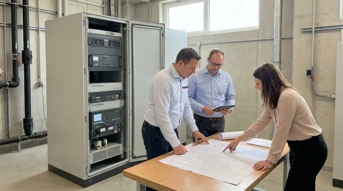
When Kord Electric installs or supports electrical work for major property buildings, we do not just “meet code.” We verify the design logic behind it. That is how we reduce risk for the owner and protect schedule. To do this, our technicians run a structured review around the fuel cell electrical limits tied to NEC Section 692.7 fuel cell maximum voltage and related requirements.
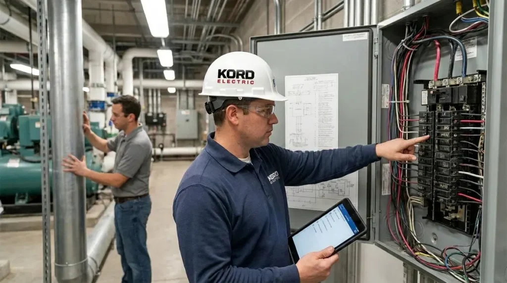
First, we confirm the system documentation clearly states the maximum output voltage under the operating conditions relevant to the installation. Then we align that information with the electrical one-line diagram, equipment ratings, and protection scheme. After that, we verify that wiring methods and termination ratings match the expected voltage and temperature conditions.
Next, we review the interface points where the fuel cell connects to the building electrical system. These interfaces include disconnects, overcurrent protection, grounding connections, and any isolation arrangements. If the design uses transfer switching, we check the switching logic and coordination, because delays or incorrect settings can create unsafe states.
Finally, we make sure the field labeling supports safe operation. And yes, we have seen labels placed like a scavenger hunt. So, we keep them clear, durable, and aligned with the actual hardware.
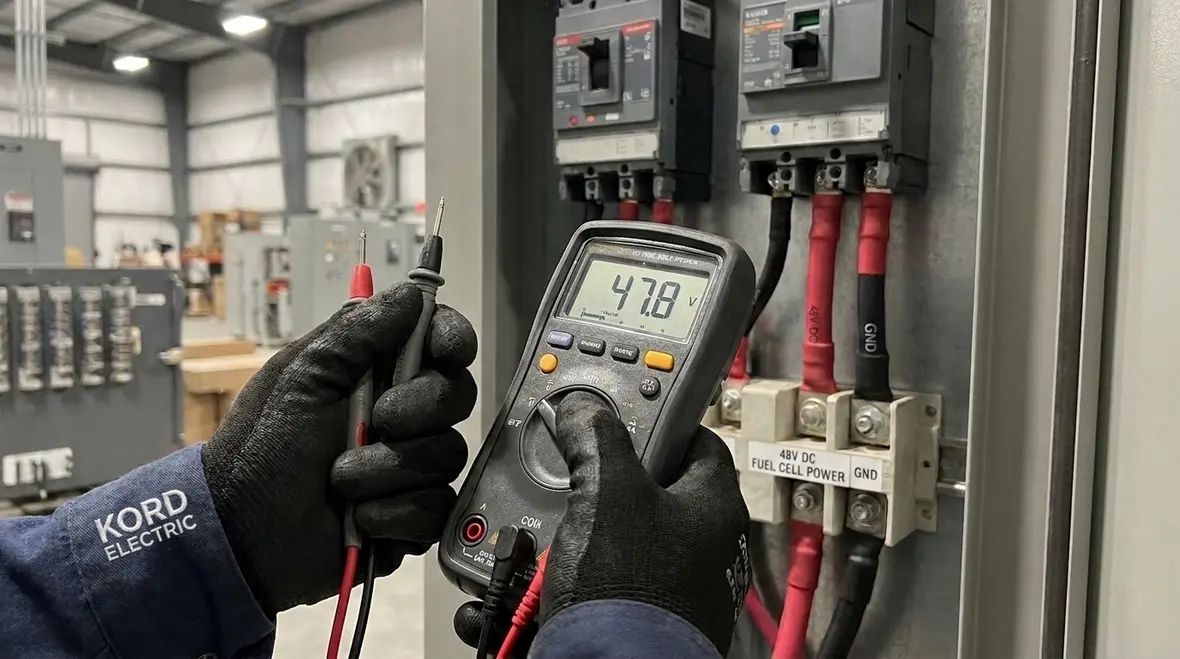
How the power path affects protection, grounding, and isolation
Commercial and industrial facilities demand predictable protection. Therefore, once you understand the fuel cell maximum voltage and output behavior, the next step is mapping how current flows through the system. From there, we can judge whether protective devices will interrupt faults quickly and consistently.
In practice, our technicians look at three layers of safety logic. The first layer is grounding and bonding, which controls fault current pathways and stabilizes system reference points. The second layer is isolation, which helps ensure safe separation between sections of the system where needed. The third layer is overcurrent protection, which matches device ratings to the voltage environment and the expected fault conditions.
Then we address the interface with other sources. Many facilities use standby generation or have battery systems, and the fuel cell must coordinate with them. As a result, we evaluate coordination settings and ensure that protection does not rely on “someone will notice it later.” Electricity punishes assumptions.
We also check for arc flash risk during maintenance. That includes reviewing the labeling, the switchgear configuration, and the conditions under which maintenance personnel could encounter energized conductors. This is where a clear understanding of the maximum voltage and the system’s operating envelope reduces uncertainty.
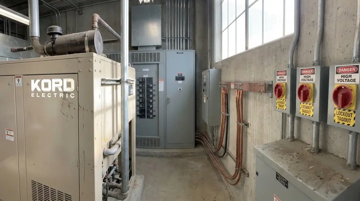
Planning and compliance for major property buildings
In major propertie buildings, compliance is a team sport. We coordinate design and construction so the electrical scope supports inspections and long-term operations. When fuel cell systems are involved, we bring extra attention to documentation and continuity between phases.
For example, we help teams align equipment schedules and field changes with the approved design intent. If a contractor swaps equipment, we confirm ratings and compatibility before the swap becomes a “surprise discovery” at testing. In addition, we help ensure that the facility’s electrical room or designated area supports safe access for maintenance and that the equipment layout matches safe working clearances.
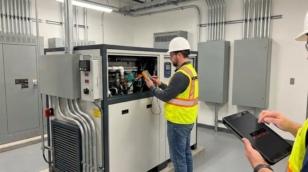
We also plan for commissioning activities. Commissioning is where the system goes from paper rules to real behavior. Our technicians review test procedures for consistency with the maximum voltage limits and verify that protection and switching operate as intended.
And when questions come up, we explain them. Our experts take time to walk facility managers through what the fuel cell system does, how to recognize normal vs abnormal operation, and where to find the key documentation. That reduces downtime during future service calls. It also prevents the classic scenario where a building team calls us because a label says one thing and the field says another. Labels should not be fan fiction.
Common mistakes we see with fuel cell maximum voltage documentation
Even strong teams make errors when schedules get tight. However, we see patterns, and we can help you avoid them early. Below are the main mistakes that show up around maximum voltage and related design requirements in commercial and industrial applications.
- Using inconsistent values across documents: One-line diagrams, equipment submittals, and commissioning plans sometimes show different maximum output figures. This creates confusion for inspection and testing.
- Ignoring interface voltage environments: Teams focus on the fuel cell stack but overlook the voltage seen by downstream components at the system connection points.
- Relying on equipment ratings without checking coordination: Even correctly rated equipment can fail to protect properly if coordination is off.
- Skipping labeling and access planning: When labels do not match field wiring, maintenance becomes slower and riskier.
- Assuming standard methods apply without review: Fuel cell systems often require careful attention to isolation and protection behavior, especially as conditions change.
Meanwhile, we keep the process calm. When our technicians explain these risks, they also show practical fixes. That includes documenting maximum voltage clearly, validating protective device selection, and confirming that installed wiring methods align with the approved design.
NEC 692.7 fuel cell maximum voltage in practice: what inspections expect
Inspections do not just “check boxes.” They look for evidence that the installation follows the NEC intent and that the system is built to handle the stated electrical limits safely. When NEC Section 692.7 fuel cell maximum voltage is part of your design basis, inspectors expect clear alignment between documents and field conditions.
At Kord Electric, we support this with thorough review and build support for commercial and industrial projects. We verify that the system’s electrical interfaces reflect the maximum voltage environment, including how conductors, terminations, disconnects, and protective devices are selected and installed.
We also emphasize operational readiness. For example, inspectors often look at whether the system includes proper labeling and whether safety disconnects and isolation components function as intended. Therefore, we prepare teams for how testing results should align with the design logic.
Finally, we make sure the maintenance and operations team can explain what they see. When others can confidently describe system behavior, the facility runs smoother and fewer issues get pushed into emergency service windows. In other words, we help you avoid the “surprise problem” that shows up after hours, like a pop quiz your building never studied for.
Where to learn more about the National Electrical Code and related guidance
If you want to go deeper into the National Electrical Code framework and how it relates to power system safety, we recommend reviewing reputable industry guidance. Kord Electric also connects our teams with relevant resources from Kord Fire, including NEC overviews and practical interpretations that help facility teams understand what matters most during design and installation.
To explore further, you can visit resources like our Kord Electric article Understanding NFPA 70: The National Electrical Code Explained for 2026 along with other electrical code explanations on what NFPA 70 covers in practical terms. You can also check our Kord Fire guidance such as the NEC-focused overview at NFPA 70: All About The National Electrical Code (NEC) 2026 for a broader safety lens that connects electrical work to life safety systems.
For major campuses and critical operations, articles like our data-focused pieces on data center power quality for reliable uptime and data center power redundancy for maximum uptime show how code-aware design decisions turn into resilient infrastructure. Combined with fuel cell guidance, they help facility teams think about coordination between everyday power distribution, backup power, and safety-driven design.
If you are evaluating systems for commercial campuses, manufacturing sites, data centers, healthcare campuses, or other major property buildings, we help you translate code language into build-ready steps. That is our role: clear explanations, precise work, and fewer surprises.
When projects move from design to implementation, having a contractor that understands both NEC requirements and local expectations is critical. Our team not only interprets NEC Section 692.7 fuel cell maximum voltage within the broader NFPA 70 framework, but also coordinates with Authority Having Jurisdiction (AHJ) expectations, test procedures, and long-term maintenance planning so the installation remains defensible years after commissioning.
How Kord Electric supports fuel cell projects from concept to operations
Fuel cell installations touch many parts of a facility’s electrical story. At early concept stages, we help owners and engineers decide how the fuel cell will integrate with existing infrastructure, from main switchboards to emergency distribution. We review how NEC Section 692.7 fuel cell maximum voltage interacts with other NEC chapters that govern grounding, wiring methods, overcurrent protection, and signage.
During design development, we analyze maximum voltage assumptions alongside likely operating modes. For example, we confirm whether the system will ever operate islanded, in parallel with utility, or as part of a microgrid that includes energy storage or solar. Each scenario influences how maximum voltage conditions appear at key buses, disconnects, and transfer points, which in turn affects device ratings and coordination studies.
On the construction side, our field teams compare drawings and specifications to real-world routing and installation choices. If conduit runs change, or if field conditions force alternative terminations, we recheck clearance, insulation, and labeling impacts so NEC-driven limits remain intact. Instead of letting “field fit” decisions drift, we connect them back to the voltage environment that the design assumes.
Once a system approaches energization, our technicians support functional testing, safety checks, and documentation updates. We help verify that maximum voltage limits used for arc flash studies, protective relay settings, and maintenance procedures all match the as-built installation, not just the original design narrative. The result is a system where operators can rely on documents during emergencies instead of wondering which version of the story is correct.
Coordinating fuel cell voltage limits with emergency and backup power
Many commercial and industrial facilities already rely on backup generators, uninterruptible power supplies, and other emergency systems. When fuel cells join the mix, the maximum voltage environment can change at transfer switches, distribution panels, and key loads. We examine how NEC Section 692.7 fuel cell maximum voltage aligns with requirements for emergency systems, especially when power can flow from multiple directions during transitions.
This coordination includes confirming that disconnects are clearly identified, that operators know under which conditions each source can energize a bus, and that overcurrent protective devices see fault currents and voltages within their intended operating windows. Poor coordination can turn a clean backup sequence into a confusing event filled with nuisance trips or, worse, non-clearing faults.
We also help facilities plan how fuel cell power supports business continuity. Pairing guidance from our emergency design work with practical experience in major property buildings, we treat each source as part of a single reliability strategy. Fuel cell voltage limits become one of the guardrails that keep protective schemes predictable, rather than a detail relegated to a spec sheet nobody reads on a busy day.
For organizations in complex jurisdictions, such as large municipalities and county-wide campuses, we align design decisions with both NEC sections and local amendments. That way, inspection conversations stay grounded in shared expectations instead of last-minute reinterpretation. Clear voltage definitions, backed by accurate diagrams and labels, make those conversations far less dramatic.
Documentation, training, and long-term maintenance around maximum voltage
After a fuel cell system passes inspection and enters service, the work does not end. Over time, buildings add loads, adjust operating schedules, or reconfigure distribution equipment. Without disciplined updates, maximum voltage assumptions can drift away from reality. We emphasize document control so that one-line diagrams, labeling, and procedures stay in sync with the actual installation.
We also train maintenance teams on how NEC Section 692.7 fuel cell maximum voltage influences their day-to-day decisions. For example, we explain why de-energization and lockout/tagout procedures must account for all possible sources, not just the most obvious breaker handle. When maintenance staff understand where fuel cell voltage might appear, they are less likely to encounter “unexpectedly energized” equipment during troubleshooting.
Another maintenance focus is planning periodic testing in a way that respects maximum voltage limits and coordination assumptions. If relays are re-set, or if new breakers are introduced during an upgrade, we help confirm that trip curves, withstand ratings, and available fault currents still match the system’s voltage profile. That reduces the chance that a quiet setting change today becomes a loud problem during tomorrow’s event.
Finally, we encourage facility leaders to treat fuel cell documentation like any other critical asset. If a facility can not easily locate its drawings, sequence of operations, and labeling schedule, then its ability to respond during an electrical incident is already compromised. Clear NEC-driven voltage limits are powerful, but only if the people in the room know where to find them and how to apply them under pressure.
Connecting fuel cell NEC compliance with broader electrical services
Fuel cell design and NEC compliance rarely exist in isolation. They intersect with load management, surge protection, emergency power, and everyday distribution upgrades. That is why working with an electrical partner experienced across commercial and industrial systems matters. At Kord Electric, the same technicians who help interpret fuel cell maximum voltage constraints also work on power quality, redundancy, and load balancing projects in major facilities.
For building owners and operators across the region, our Los Angeles County electrical services offering supports everything from new system design to maintenance and troubleshooting. That means your fuel cell is not just bolted onto an existing system; it is integrated into a coordinated plan for safe, reliable power.
Whether you are planning a first fuel cell installation or expanding a site that already runs multiple distributed energy resources, we help keep NEC Section 692.7 fuel cell maximum voltage, NFPA 70 guidance, and practical operating realities aligned. The result is simple: fewer surprises, fewer emergency calls, and a system that behaves the way the drawings promised.
FAQ
Conclusion and CTA
Fuel cell projects succeed when the electrical design matches the rules and the field matches the drawings. NEC Section 692.7 fuel cell maximum voltage is not just a reference number, it is a practical guardrail that drives safe protection, grounding, and isolation decisions for commercial and industrial facilities. At Kord Electric, our technicians and expert service staff help you translate code intent into build-ready steps, then verify what we install during commissioning. If you are planning a fuel cell system, contact us for a code-aligned review and dependable execution.
From early concept conversations through final inspection and long-term maintenance, we work to keep your project on the right side of both the NEC and real-world reliability. By treating NEC Section 692.7 fuel cell maximum voltage as a central design parameter instead of a footnote, you give your facility a stronger foundation for safe operation, easier inspections, and calmer days for everyone who depends on that power.
If you are ready to move from “we will figure it out later” to a structured, code-aware plan for your next fuel cell or advanced power project, our team is ready to help you align design, documentation, and installation.