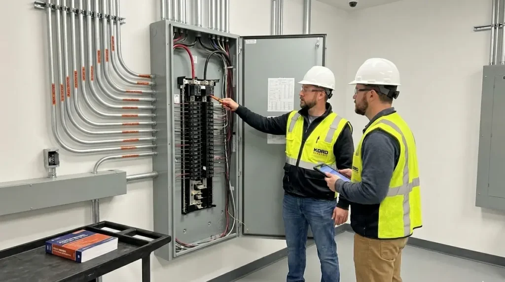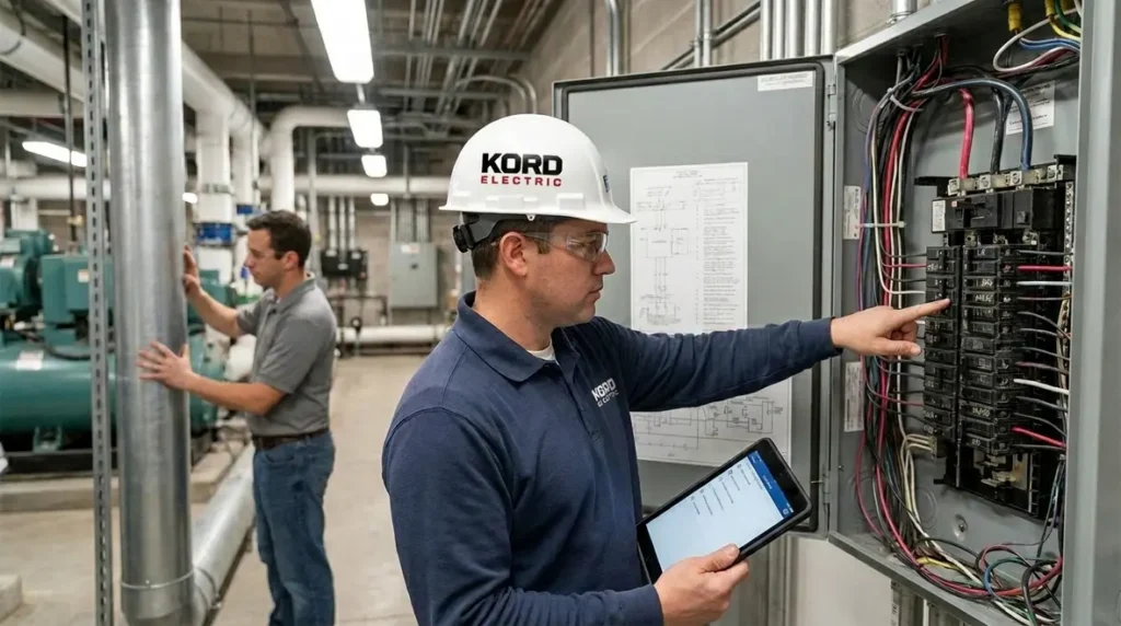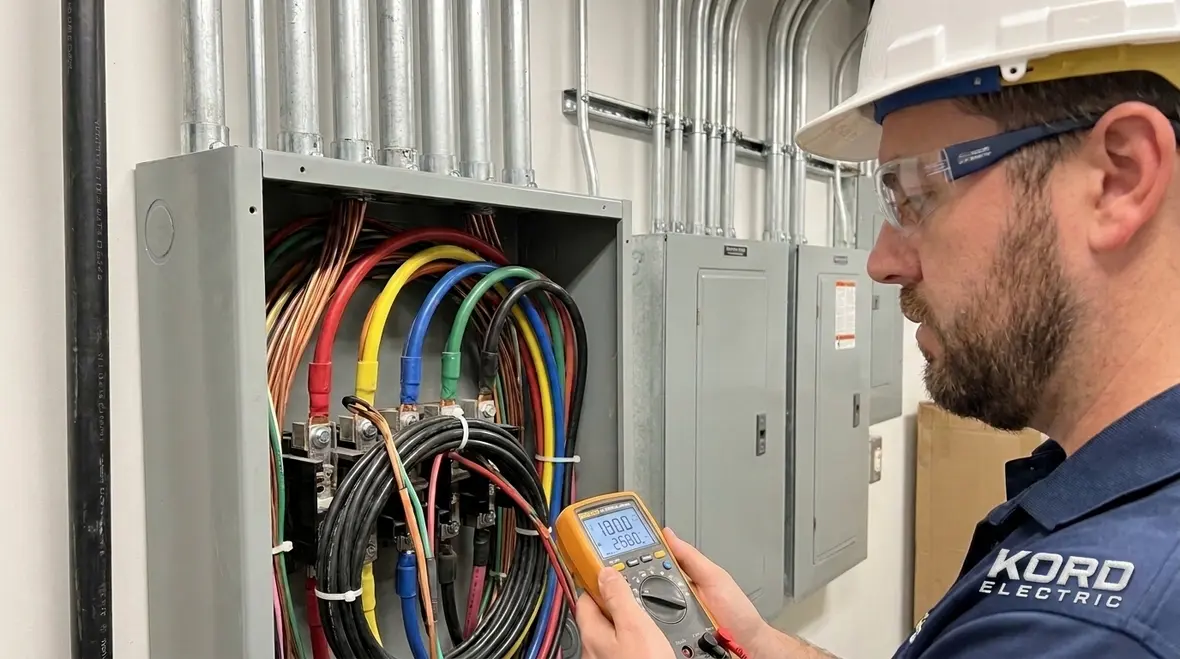
NFPA 70 Ampacity Basics: NEC Rules for 0 to 2000 Volts
At Kord Electric, we see it every week: someone wants power, and then reality shows up wearing a hard hat. The NEC covers how much current a wire can safely carry, and NFPA 70 Section 310.14 sets the tone for conductors used at 0 to 2000 volts. In this guide, we walk through the core NEC ampacity 0 to 2000 volts rules in plain language, so facility leaders, electrical contractors, and in house teams can plan smarter and avoid costly mistakes.
And yes, amps can be as dramatic as a superhero origin story, except the villain is heat, and the heroes are good engineering choices. Our technicians explain the “why” behind the rules, step by step, so the decisions hold up under real world load conditions.
What Section 310.14 Actually Controls for Conductors
NFPA 70 Section 310.14 focuses on how conductors are rated and how ampacity rules apply when the system uses voltages under 2000 volts. First, it makes sure the conductor chosen can handle the load current without overheating. Then, it governs how you adjust those ratings when conditions change.
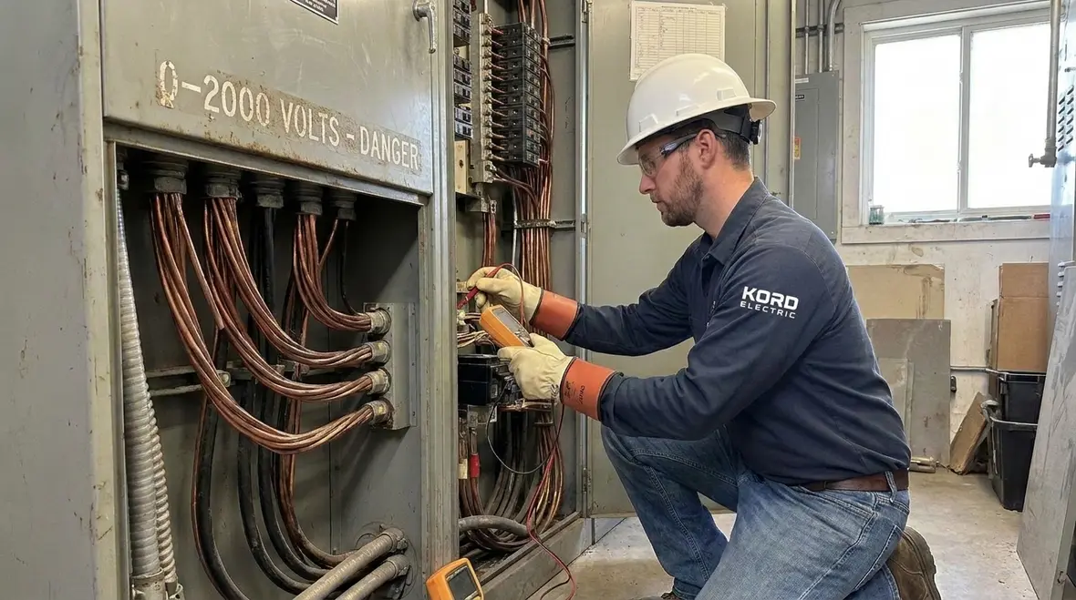
That second part matters. In commercial and industrial facilities, conditions rarely stay “ideal.” Temperature swings, bundling, conduit fill, insulation type, and operating environment all affect conductor heat. Therefore, you cannot treat ampacity like a static label you slap on a drawing and forget. Instead, we help teams apply adjustments so the design matches the jobsite.
To keep it practical, our expert service staff explains this in a way that project teams can use during design reviews and commissioning. We do not just point to a rule. We show how the rule connects to actual installation layouts, and how it influences conductor size, raceway planning, and long term reliability.
When facility teams want a wider code backdrop, we often pair these discussions with resources like Understanding NFPA 70: The National Electrical Code Explained for 2026, which shows how Section 310.14 fits into the overall NEC picture for modern projects.
How We Apply NEC Ampacity 0 to 2000 Volts in Real Designs
When we plan a commercial or industrial electrical system, we start by aligning conductor selection with load calculations and then we match ampacity to the conditions of installation. Next, we verify that the circuit protection device and conductor ratings work together the way the NEC expects.
In many projects, the biggest risk does not come from misunderstanding the main tables. It comes from skipping the adjustment steps that follow the tables. For example, when conductors share raceways or sit near heat sources, their ability to carry current can drop. Consequently, the “right” conductor size may need to change once the layout becomes real.
Our technicians also stress documentation. Facility owners and maintenance teams need clear records for future work, and inspectors need clean logic for why conductor sizes and ratings align. That is how we keep the design defensible and serviceable years later.
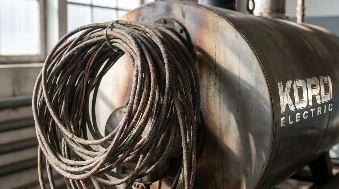
In larger projects, we often connect ampacity planning with broader NEC scope discussions, using guides like the 2026 NEC application requirements guide and NFPA 70 scope overview to keep all stakeholders aligned on when and how each rule applies in the field.
Temperature, Insulation, and Where Heat Shows Up First
Heat is the quiet failure mode. It degrades insulation, raises resistance, and increases the odds of nuisance trips or long term damage. Therefore, the conductor temperature environment plays a direct role in how we select wire size and insulation type.
Insulation rating and conductor construction set the baseline. However, Section 310.14 expects you to account for installation and ambient conditions that shift the conductor’s effective operating temperature. If the installation runs in areas with higher ambient temperatures or heat sources nearby, the design must reflect that reality.
Our team often uses a simple rule of thumb when explaining it to others: if the wire will live in a warm neighborhood, it needs to act like it. Then we translate that into the exact adjustment logic the code requires, so nobody has to guess later when the building starts behaving differently than the first walk through suggested.
And for the record, “we’ll just see how it goes” is not a design method. It is a reality show. Unfortunately, in electrical work, the audience is sometimes the insurance company.
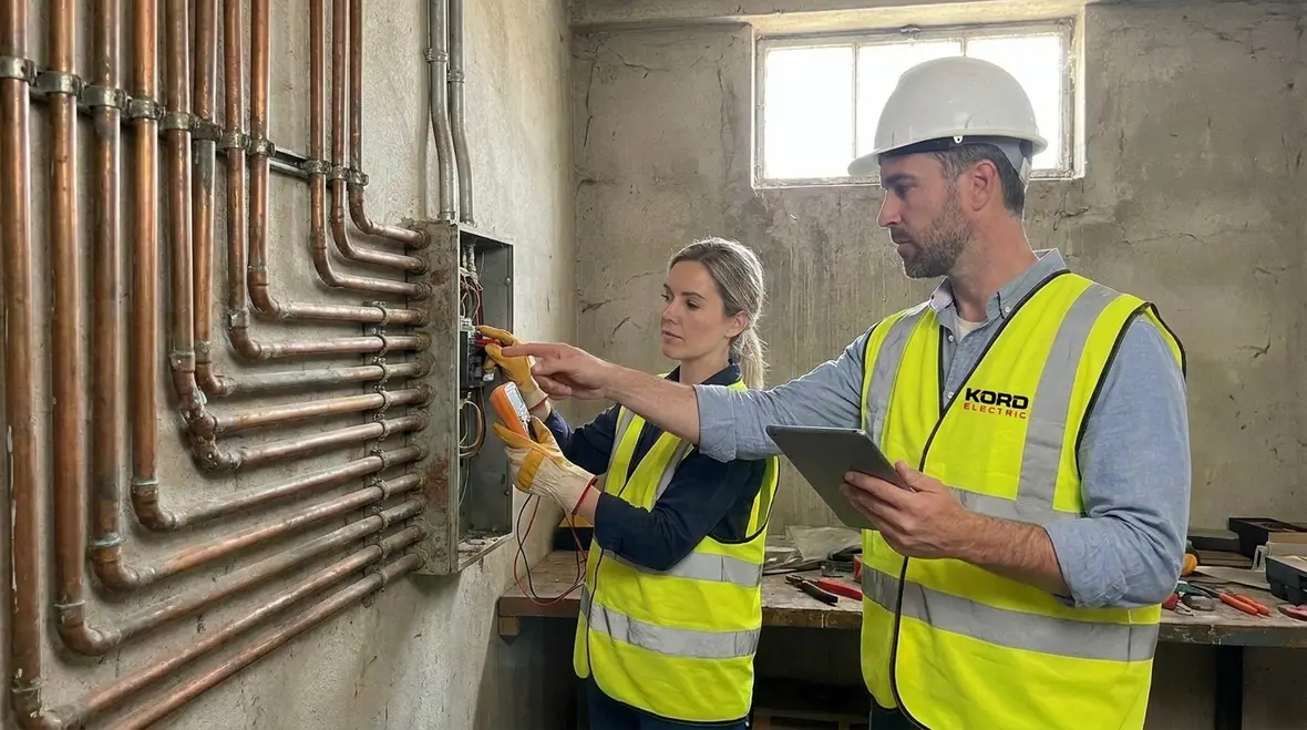
When facilities want to connect temperature and insulation topics to wider load and branch circuit strategy, we sometimes reference focused NEC breakdowns like NFPA 70 Section 120.4 specific purpose load calculations or branch circuit scope explainers, then loop the conversation back to the conductor level where ampacity lives.
Conductor Grouping and Load Centers: Adjusting Ampacity for Installation
In multi circuit panels, feeder runs, and backbone systems, conductors often share space. When multiple current carrying conductors run together, they heat each other. Then, the conductor ampacity effectively decreases because the bundle cannot shed heat as easily.
At this point, teams should look closely at how the conductors are grouped and where they run. We encourage others to think in terms of physical installation, not just electrical one line diagrams. For example, a set of parallel feeders in one raceway behaves differently than the same conductors spread out across separate pathways.
Our technicians explain the grouping logic using a simple path: identify the conductor set, confirm the arrangement, and apply the correct adjustment approach. Next, we verify the result against the circuit requirements. This prevents undersizing and reduces the chance of later “panel redesign” calls that waste time and budget.
For large property buildings, especially those with phased construction or tenant turnover, this approach also helps maintain consistent power performance across expansions.

In many of these load center conversations, we also look at how feeder minimum rating rules under NFPA 70 Section 215.4 feeder minimum rating size interact with the conductor grouping choices, so the whole distribution path stays consistent with NEC expectations.
Voltage Range, Limits, and Coordination for Commercial Power
Section 310.14 connects ampacity rules to the voltage range used. When the system operates at 0 to 2000 volts, designers and installers apply the relevant conductor ampacity methods within that scope. As a result, correct conductor sizing supports stable operation and reduces heat related wear.
However, ampacity does not stand alone. Coordination matters. Facility teams need to ensure the selected conductor ampacity fits the protection approach used for overcurrent protection, grounding, and system design philosophy. We help others review the full chain: load calculation, conductor selection, raceway constraints, and protective devices.
We also remind property leaders that good coordination reduces service disruptions. When something trips repeatedly, maintenance teams waste hours chasing symptoms instead of solving the root cause. We want the system to behave predictably, because commercial and industrial facilities run on schedules, not surprises.
And yes, the electrical code can feel like a maze at first. But when our expert staff walks you through it, the path becomes clear, like finding the right episode in a streaming service without the “are you still watching?” anxiety.
For deeper coordination topics, especially around protection and arc energy, we often connect clients with focused guides such as Kord Electric’s article on NEC arc flash breaker features and NFPA 70 240.87, which illustrates how protective device settings and features support safe operation alongside correct ampacity.
Working With Kord Electric: How We Support NEC Compliance and Service Readiness
Kord Electric supports commercial and industrial facilities and major property buildings. We do not target small residential work, because the needs in commercial power systems require deeper planning, tighter documentation, and stronger long term service thinking.
Our approach stays practical. We review drawings and conductor selections early, so ampacity and installation details match the real layout. Then our technicians help teams understand the code logic behind conductor adjustments, not just the final sizes. When a facility team asks why a change happened, we can explain it clearly, in plain language, without making anyone feel like they need a law degree.
For ongoing operations, we also support service readiness. Clear labeling, organized raceway documentation, and accurate as built records make future maintenance faster and safer. When another contractor or facility electrician arrives later, they get answers quickly instead of guessing.
For more NEC background and code context, we direct people to our resources at kordelectric.com and code focused pages at kordfire.com, because understanding the code helps us build systems that stand up to real use. Many facility leaders start with high level explainers like Kord Fire’s NFPA 70: All About The National Electrical Code (NEC) 2026 and then zoom into Kord Electric’s project ready guidance for commercial buildings.
When these planning conversations turn into real projects, teams in Southern California often connect this ampacity and compliance work with local support through our Los Angeles County electrical services overview, which outlines how we help guide systems from design through inspection and long term operation.
FAQ: NEC Ampacity and Section 310.14 Quick Answers
Conclusion: Keep Your Power System Reliable, Start With Correct Ampacity
When we handle commercial and industrial projects, we treat ampacity like a safety feature, not a paperwork exercise. NFPA 70 Section 310.14 and the NEC ampacity approach for 0 to 2000 volts help us size conductors correctly, adjust for real installation conditions, and reduce heat related failures over time. If you are planning, upgrading, or auditing a major property electrical system, contact Kord Electric. Our technicians explain the details and help you move forward with confidence, not guesswork.