NEC AC GEC Sizing for NFPA 70 Section 250.66
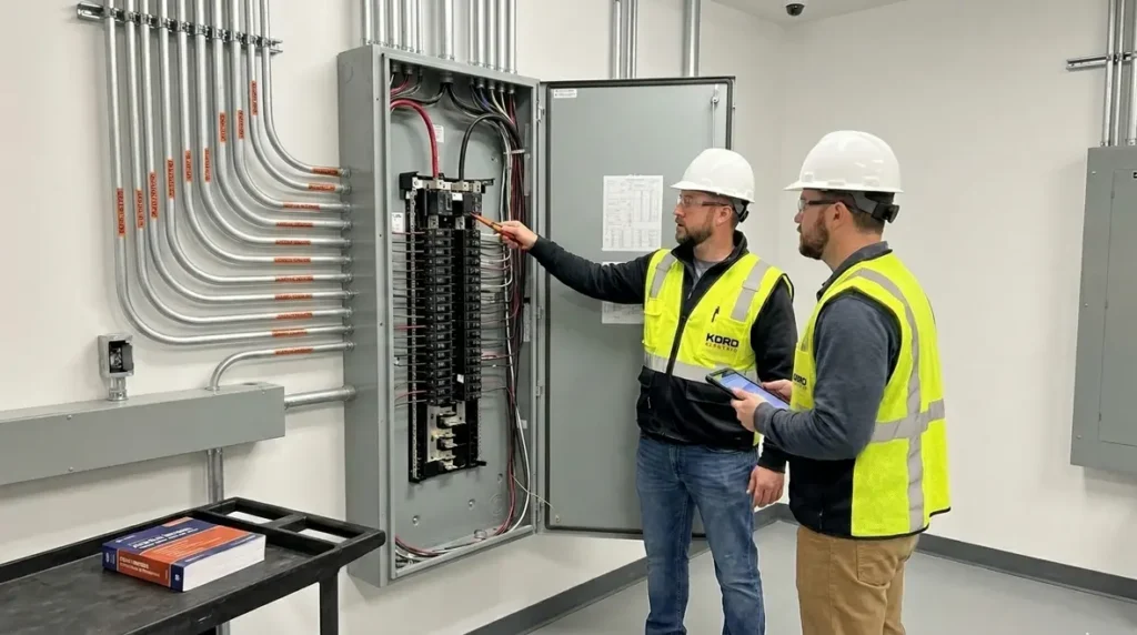
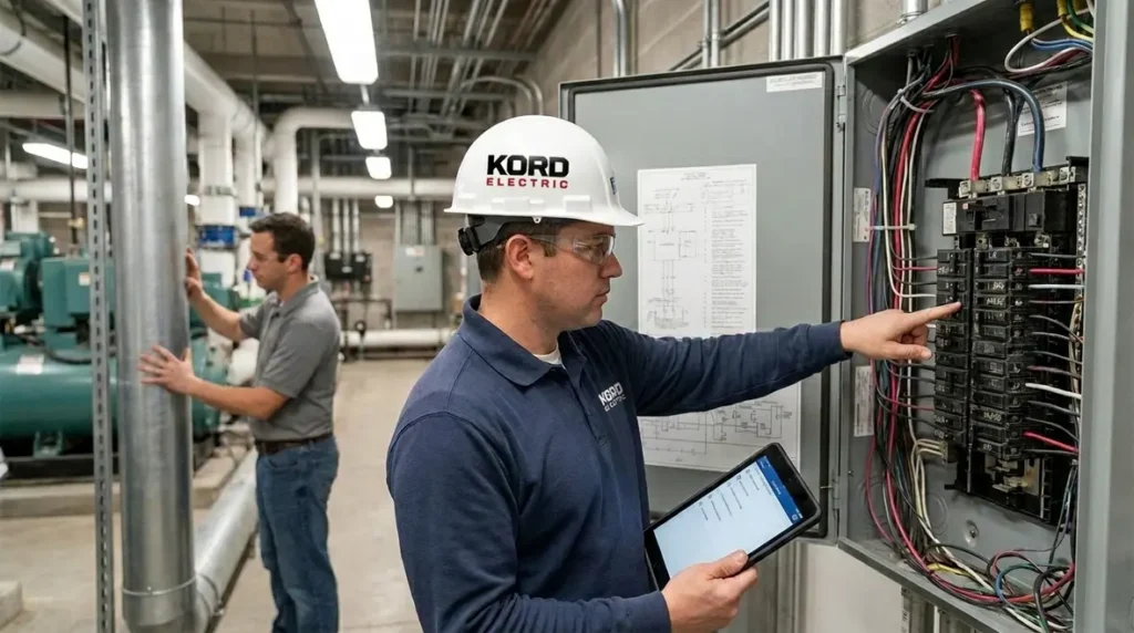
When a commercial or industrial facility needs a solid electrical foundation, we start with NEC AC GEC sizing under NFPA 70 Section 250.66. In plain terms, we size the alternate current grounding electrode conductor so it can handle fault current and help protect people, equipment, and the building’s electrical system. At Kord Electric, our technicians and expert service staff guide teams through this step with calm, hands-on clarity. And yes, we know paperwork can feel like it was written by a committee that never had to troubleshoot in the rain. Still, we make the code practical, not mysterious. So, whether your site is a hospital, a manufacturing campus, or a major property building, we explain how 250.66 connects to the rest of the grounding plan, and we size it correctly the first time.
Why NFPA 70 Section 250.66 matters for commercial electrical systems
NFPA 70 Section 250.66 focuses on the sizing of the grounding electrode conductor used for alternating current, and it matters because grounding is not a “set it and forget it” detail. In the real world, grounding protects during abnormal conditions, and it helps stabilize voltages when faults occur. Therefore, when we undersize the AC grounding electrode conductor, the system may not perform as required. Meanwhile, when we oversize it without a plan, we can create unnecessary cost and installation complexity.
In addition, commercial and industrial buildings often have multiple paths for electrical equipment, lightning protection systems, bonding jumpers, and service equipment all tied to grounding. That means the grounding electrode conductor size becomes part of a larger safety chain. As a result, we treat 250.66 as one link in a chain that includes bonding and electrode connections, rather than a standalone rule pulled from a textbook.
Our expert service staff at Kord Electric often sees the same pattern during reviews. Someone installs bonding conductors one way, then later the project team discovers the AC grounding electrode conductor size does not match the service situation described in the code. Then the field team scrambles. So, we plan it early, confirm the facility details, and keep the grounding system consistent from design through install.

Understanding AC grounding electrode conductor sizing in plain terms
To apply NFPA 70 Section 250.66 correctly, we first identify what the code calls the AC grounding electrode conductor. Then we link its conductor size to the appropriate reference values based on the service arrangement. Even though the text looks technical, the decision process is practical when we walk it step by step.
Here is the core idea we keep consistent for our commercial and industrial customers. The conductor must be large enough to carry fault current or otherwise meet the performance requirement for grounding electrodes tied to the service. Furthermore, the conductor size must reflect the service conductor rating and the applicable rules used for grounding electrode conductors.
However, we also remind teams not to confuse the AC grounding electrode conductor with other grounding elements. For example, bonding conductors that connect metal parts differ in purpose and rules. Likewise, equipment grounding conductors that run with branch circuits serve a different job. So, we make sure each conductor has a role and a size that fits that role.
One of our technicians likes to put it this way: grounding conductors are like good leadership. If everyone tries to lead the whole team, nobody gets the job done. Each grounding part has a job, and we size it so it can actually do it.
Connecting NEC AC GEC sizing to the broader NEC grounding picture
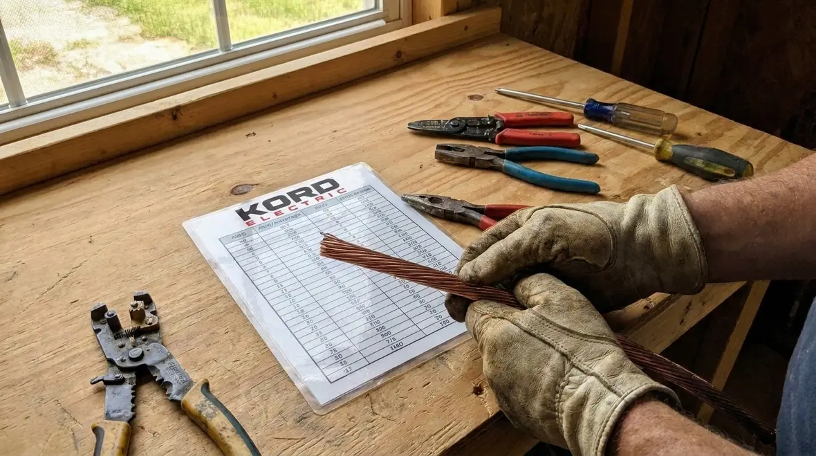
For many commercial properties, NFPA 70’s grounding rules can feel scattered across sections. Our team connects those dots so NEC AC GEC sizing fits with the rest of your grounding and bonding plan. When facility leaders want a bigger-picture look at how 250.66 sits inside the code framework, we often point them to resources like our guide on Understanding NFPA 70: The National Electrical Code Explained for 2026, which walks through the structure of the NEC and how grounding and bonding interact with other protection rules for large facilities.
How we verify the service and electrode setup before sizing
Before we touch a conductor size, we verify the building’s electrical reality. That matters because NFPA 70 Section 250.66 depends on how the electrical service is set up, and the site details shape what the “right” size means. In practice, we gather key information first, and then we confirm the electrode system and the bonding points.
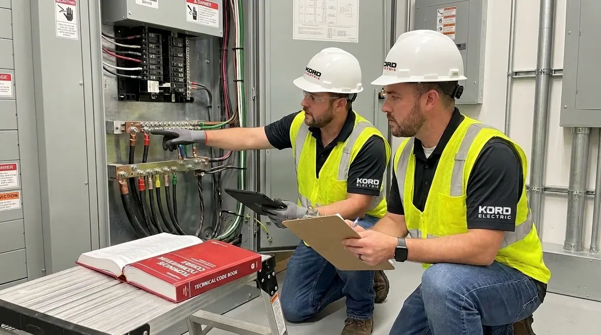
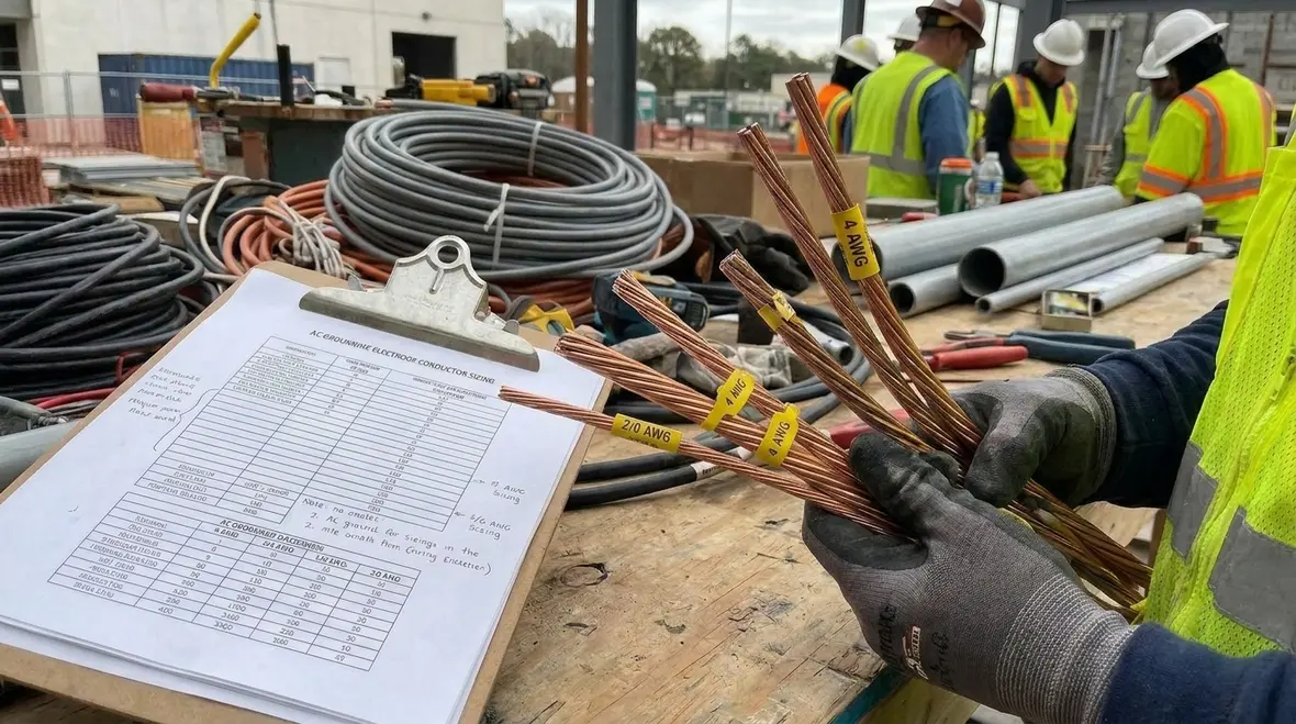
At Kord Electric, our process for NEC AC GEC sizing starts with the service equipment description, the electrical service parameters, and the grounding electrode system shown in the drawings. Next, we confirm which electrode(s) the system uses, and we check how the AC grounding electrode conductor will connect to those electrodes. Also, we look at whether the facility has multiple services, whether the system includes separate grounding arrangements, and how the grounding conductors route in the field.
Then we check for practical conflicts that can undermine compliance. For instance, conduit fill limits, route length, termination method, and conductor material can all affect what gets installed. Therefore, we do not treat sizing as a math exercise only. We treat it as a design and installation decision that must survive the field.
In addition, we follow the guidance style found in the code explained by our partners and education resources on national electrical code topics, because clarity saves money and time. When we explain the rules, our goal is simple: reduce guesswork for the facility and keep the documentation clean for inspection.
Linking service verification to broader NEC planning
Because NEC AC GEC sizing does not live in isolation, we routinely connect this verification step to broader planning work for commercial facilities. When owners are already thinking about panel upgrades, tenant improvements, or long-term modernization, we align grounding reviews with bigger planning frameworks like our Electrical Infrastructure Upgrade Planning Guide and design resources such as Building Electrical System Design: Planning Power for Commercial Facilities. That way, grounding electrode decisions support the next decade of electrical work, not just the next inspection.
Common installation mistakes we prevent on major property projects
Commercial and industrial facilities often share the same “hidden potholes” when it comes to grounding. Even strong teams can miss something when timelines get tight and multiple trades work at once. So, we prevent problems by focusing on the details that most failures come from.
First, we see mismatched conductor sizes between design intent and field install. Sometimes the spec shows one size, but the contractor uses what they commonly stock. That works until it does not, and then the inspector asks for proof. Then the project team has a meeting that nobody wants.
Second, we see incorrect assumptions about what conductor belongs where. A grounding electrode conductor connection point might get treated like an equipment bonding point. Yet the code logic differs, and that mismatch can create compliance issues. We correct that early by labeling and confirming connection diagrams.
Third, we see route and termination shortcuts. If the AC grounding electrode conductor has poor termination or inadequate contact, the system may not provide the intended performance. Therefore, we verify termination method and torque specifications with the same seriousness used for critical electrical connections.
Finally, we see teams forget about continuity. When conductors or electrodes get connected in phases during construction, temporary conditions can leave gaps. Even if the system looks complete on day one, we confirm continuity and final bonding as the project closes.
And yes, we do use a little humor to keep people focused. We tell our crews that grounding failures are the only kind of “ghost stories” you do not want to meet in a transformer room. Then we move on to the work.
Coordinating NEC AC GEC sizing with safety and maintenance practices
To keep these mistakes from repeating, we connect grounding reviews to a larger safety and maintenance rhythm. For example, on sites that adopt structured safety practices like those in our Commercial Electrical Safety Protocols Guide, we fold NEC AC GEC sizing checks into pre-energization reviews and ongoing maintenance walkdowns. That keeps grounding performance visible instead of treating it as a one-time design decision that everyone forgets after the as-builts are filed.
Documentation and inspection support for NEC compliance
Code compliance is not only about what gets installed. It also includes how the project team documents the approach and how they support it during inspection. At Kord Electric, we help commercial and industrial stakeholders keep their records in order, so the inspection process stays calmer.
When we handle grounding electrode conductor work, we typically support the project with clear calculations, a grounding one line review, and installation notes that align with NFPA 70 requirements. Moreover, we make sure the sizing tied to NEC AC GEC sizing matches the service description and the electrode system shown in the drawings.
Because facilities often have repeat work across campuses and major buildings, we also standardize how we present our findings. That means the next project team does not start from zero. Instead, they can build on prior compliance decisions, adjust for site differences, and move forward with less friction.
Our approach also fits the broader national electrical code training mindset shown in resources we reference for NEC context, including how the code gets explained for readers who need clarity fast. We do not treat compliance as a “read it once” task. We treat it as a process of verification, review, and field alignment.
Using NEC resources to keep teams aligned
When sites want more background without diving straight into dense code text, we often combine NEC AC GEC sizing workshops with reading paths through resources like our article on How to Read NFPA 70: National Electrical Code and primers such as What Is NFPA 70? Understanding the National Electrical Code. That way, technicians, engineers, and facility managers share the same language when they talk through grounding electrode conductors, bonding, and fault performance.
FAQ: NFPA 70 Section 250.66 and AC grounding electrode conductor sizing
Schedule a grounding review with Kord Electric
If your team is planning a new commercial or industrial project, upgrading service equipment, or addressing grounding questions before an inspection, we can help. Our technicians and expert service staff review the service setup, confirm the electrode connections, and support NEC AC GEC sizing decisions so the grounding system performs the way the code intends. We also coordinate these reviews with broader electrical work, whether you are modernizing existing infrastructure or planning upgrades through services such as our dedicated Los Angeles County commercial electrical services, so grounding and bonding stay aligned with the rest of the power system.
Contact Kord Electric to schedule a grounding electrode conductor review and get clear, jobsite-ready guidance. We keep it calm, we keep it accurate, and we avoid the “surprise meeting” nobody asked for.
For facility leaders building a roadmap beyond a single project, it also helps to explore related planning resources on our blog, from modernization overviews like Modernize Commercial Building Electrical Systems to high-level NEC primers such as Commercial Electrical Systems for Modern Buildings. Together with focused NEC AC GEC sizing support, these guides help your team connect day-to-day work with long-term reliability and code compliance.
When you are ready to move from questions to action, we are ready to help your facility turn grounding requirements into a stable, documented, and easy-to-maintain part of your electrical system.